Device and method for testing bonding strength of rivet type multilayer electrical contact

A testing device and bonding strength technology, applied in the direction of measuring device, strength characteristics, and testing the strength of materials by applying stable tension/pressure. The effect of good scientific research application value, credible principle and simple structure

Inactive Publication Date: 2018-08-03
HARBIN INST OF TECH
View PDF0 Cites 4 Cited by
  • Summary
  • Abstract
  • Description
  • Claims
  • Application Information

AI Technical Summary

Problems solved by technology

[0004] In order to solve the problem that the existing method for measuring the bonding strength of a rivet-type multi-layer electrical contact cannot directly measure the actual bonding force-displacement curve of the multi-layer, the present invention further provides a device for testing the bonding strength of a rivet-type multi-layer electrical contact and test methods

Method used


Image

  • Device and method for testing bonding strength of rivet type multilayer electrical contact
  • Device and method for testing bonding strength of rivet type multilayer electrical contact
  • Device and method for testing bonding strength of rivet type multilayer electrical contact

Examples


specific Embodiment approach 1

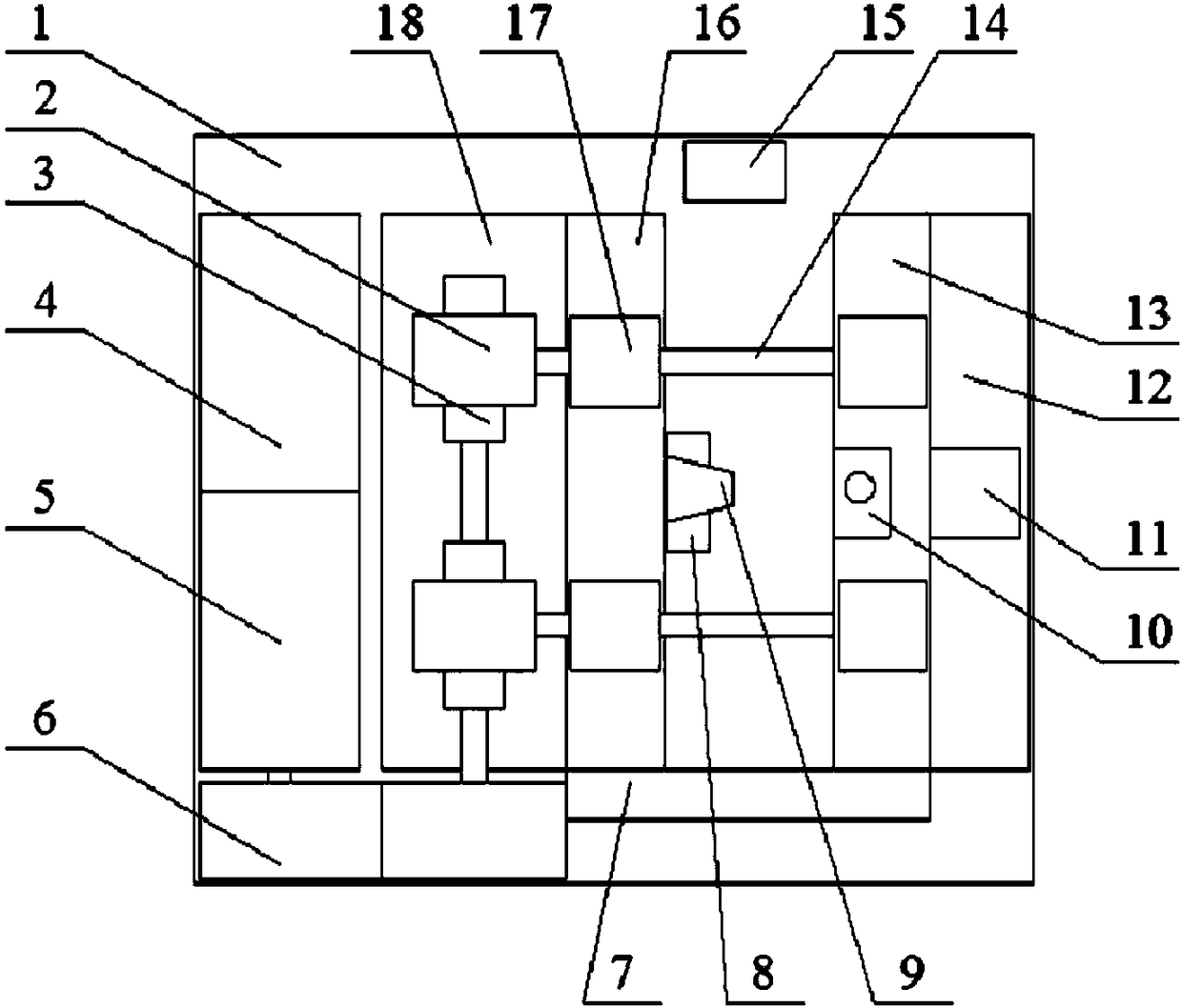
[0023] Specific implementation mode one: as Figure 1~3 As shown, the rivet-type multilayer electrical contact bonding strength testing device of this embodiment includes a base 1, two worm wheels 2, two worms 3, a motor 4, a reducer 5, two gears 6, an encoder 7, a pusher Head 8, electric lifting slide table 9, fixture 10, force sensor 11, support seat 12, first screw support 13, two bidirectional lead screws 14, industrial camera 15, second screw support 16, four nuts 17 and a fixed seat 18; the motor 4 and the reducer 5 constitute the driving unit, the two gears 6 constitute the transmission unit, the electric lifting slide table 9, two two-way lead screws 14 and the industrial camera 15 constitute the test unit, the push head 8 and the fixture 10 The test piece fixture is constituted, the encoder 7 and the force sensor 11 constitute the test unit, and the two gears 6 are composed of a driving gear and a driven gear; the driving unit, the fixed seat 18, the second screw supp...

specific Embodiment approach 2

[0025] Specific implementation mode two: as figure 1 As shown, the base 1 of this embodiment is a rectangular plate base. Such design is convenient for processing and making. Other components and connections are the same as those in the first embodiment.

specific Embodiment approach 3

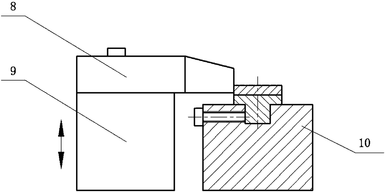
[0026] Specific implementation mode three: as figure 1 As shown, in this embodiment, the push head 8 is located in the middle of the second screw support 16 , and the clamp 10 is located in the middle of the first screw support 13 . Such a design can ensure the centering of the test piece during the movement of the test device in the opposite direction or backward direction, and at the same time, the present invention has the characteristics of large working force and compact structure. Other compositions and connections are the same as those in Embodiment 1 or 2.


PUM


Abstract

The invention relates to a device and a method for testing bonding strength, in particular to a device and a method for testing bonding strength of a rivet type multilayer electrical contact and solves the problem that actual bonding force-displacement curves of multiple layers cannot be measured directly with existing methods for measuring the bonding strength of the rivet type multilayer electrical contact. Two two-way lead screws are arranged in parallel, a worm gear is mounted at one end of each two-way lead screw, each worm gear is meshed with one corresponding worm, a second lead screw support is fixedly connected with two nuts on the same side, and a first lead screw support is fixedly connected with another two nuts on the same side. An experiment unit and a test unit are reset; adrive unit of the test device is started to drive a push head and a fixture to move oppositely at the constant speed from two ends of the test device in a centered manner; in the process that the pushhead and the fixture slowly move from two ends of the test device to the middle, an industrial camera is finely adjusted, and clear dynamic images of a computer are obtained. The device and the method are used for testing the bonding strength of the rivet type multilayer electrical contact.

Description

technical field [0001] The invention relates to a test device and a test method for testing the bonding strength of a rivet-type multilayer electric contact, belonging to the field of instruments and electric contacts. Background technique [0002] Rivet-type multilayer electrical contacts are widely used in various contactors, relays and switches, and their quality largely determines the performance and reliability of electrical products. One of the key factors for the quality of electrical contacts. At present, the most common methods for measuring the bonding strength of rivet-type multilayer electrical contacts are flattening method and heat treatment method. Both methods need to cut the flattened or heat-treated rivet, polish the section, measure the crack length and other parameters with a projector or reading microscope, and then use the formula to calculate the relevant parameter ratio as a judgment of the bonding strength of the electrical contact. reference basis...

Claims


Application Information

Patent Timeline
Patent Type & Authority Applications(China)
IPC IPC(8): G01N3/16G01N3/06
CPCG01N3/165G01N3/06G01N3/068G01N2203/0037G01N2203/0647G01N2203/0676G01N2203/0682
Inventor 任万滨杜扬赵明
Owner HARBIN INST OF TECH
Why Eureka
Try Eureka