Method and system for optical fiber identification through fusion splicer and special core regulation support

An optical fiber fusion splicer and optical fiber technology, which is applied to the coupling of optical waveguides, light guides, optics, etc., can solve the problems of occupying a large space, increasing the manufacturing cost, and complicated operation of the focusing mechanism, so as to achieve convenient industrial processing and production, and a specific structure. Effect

Active Publication Date: 2018-08-03
NANJING JILONG OPTICAL COMM
View PDF7 Cites 7 Cited by
  • Summary
  • Abstract
  • Description
  • Claims
  • Application Information

AI Technical Summary

Problems solved by technology

The existing solution is to achieve the purpose of focusing through the movement of the objective lens. To achieve the movement of the objective lens in the optical fiber fusion splicer, an additional focus adjustment mechanism is required. The focus adjustment mechanism contains two or more motors, and the objective lens is driven by the motor. Move back and forth to achieve zooming, but the operation of the focusing mechanism is complicated, takes up a lot of space, and increases manufacturing costs

Method used


Image

  • Method and system for optical fiber identification through fusion splicer and special core regulation support
  • Method and system for optical fiber identification through fusion splicer and special core regulation support
  • Method and system for optical fiber identification through fusion splicer and special core regulation support

Examples


Embodiment Construction

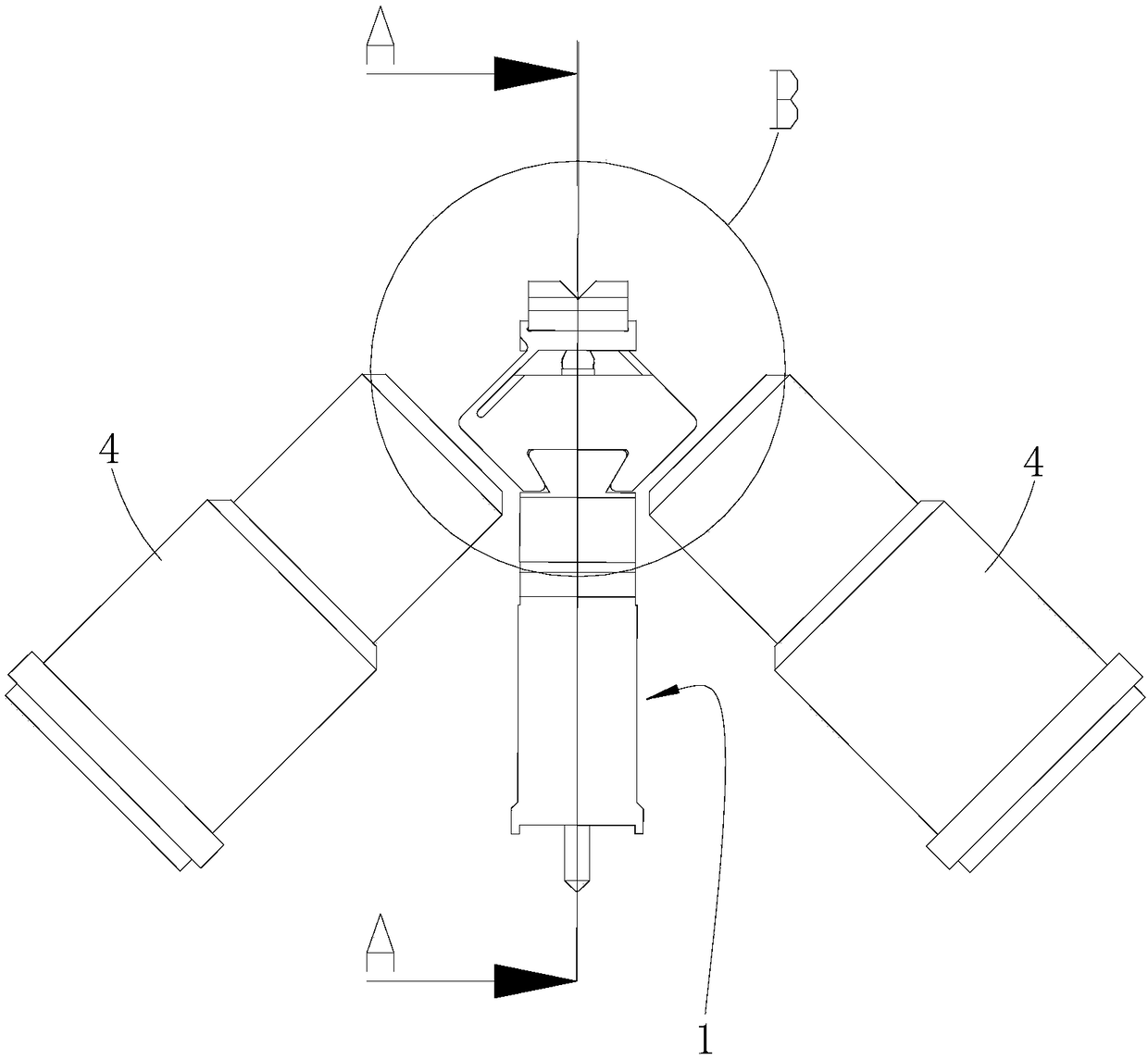
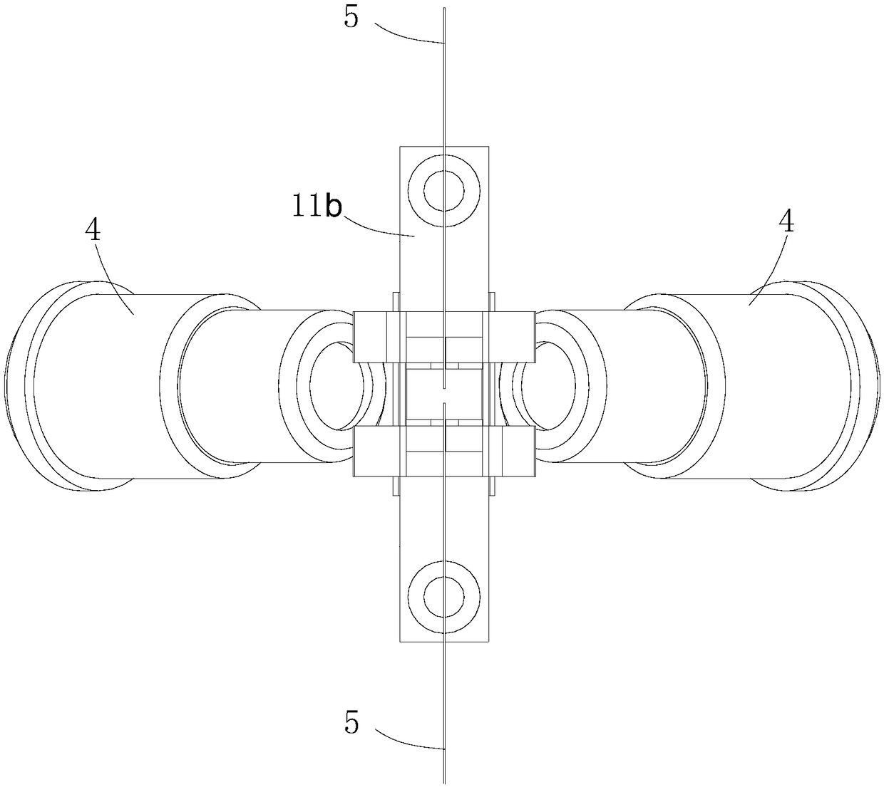
[0051] Such as Figures 1 to 5 as shown ( Figure 5 The section direction of image 3 same section direction)

[0052] The structure of the special alignment bracket is firstly introduced below. The alignment bracket includes a housing 1 , two sets of adjustment components and two sets of optical fiber positioning blocks 3 .

[0053]The housing 1 includes a housing body 11 and an installation baffle 12. The housing body 11 is provided with two first adjustment stage holes 11a that pass through its upper and lower end surfaces. The installation baffle 12 corresponds to the position of the first adjustment stage hole 11a of the housing body 11. There are two second adjustment stage holes 12a, and the installation baffle 12 is at the lower part of the shell body 11 through fastening screws (not shown in the figure), and the first adjustment stage hole 11a of the shell body 11 corresponds to the first adjustment stage 12 of the installation baffle 12 The two adjustment stage ho...


PUM


Abstract

The present invention provides a method for optical fiber identification through a fusion splicer. The method comprises the following steps of: putting optical fibers on a core regulation support; moving the optical fibers in an optical axis of an objective lens of the fusion splicer through the core regulation support; and collecting signals through the objective lens and the CCD to determine thetype of the optical fibers. Devices on a current welding device can be reused with no need for adding a focusing mechanism. The present invention further provides a system for optical fiber identification through a fusion splicer. The system comprises a core regulation module, a collection module, a comparison module, a selection module and a transmission module. The present invention further provides a special core regulation support for achieving the method for optical fiber identification through a fusion splicer. A housing is internally provided with two regulation holes, an elastic member of a regulation module is provided with a through hole on the housing, a swing bar is extended on the elastic member, a transfer bar penetrates the through hole and the regulation holes, a steel ball is put at the transfer bar and the swing bar, and an optical fiber location block is fixed on the swing bar and is provided with a spacing groove. The core regulation support drives the optical fibers to complete movement so as to meet the design requirement of the method for optical fiber identification.

Description

technical field [0001] The invention relates to a method for identifying optical fibers by an optical fiber fusion splicer. [0002] The invention also relates to a system for identifying optical fibers by an optical fiber fusion splicer. [0003] The invention further relates to a special core-adjusting support for the method for identifying optical fibers of an optical fiber fusion splicer. Background technique [0004] The fiber fusion splicer is used to splice a variety of optical fibers. During the splicing operation, different types of optical fibers generally need to set different splicing parameters. The image-based optical fiber identification method generally changes the optical fiber image through focusing and other optical devices, and analyzes Compare these changes to determine the type of fiber. Relative movement between the optical fiber and the objective lens (that is, the defocusing and zooming process of the observed object), for example, for G.652, G.653...

Claims


Application Information

Patent Timeline
Patent Type & Authority Applications(China)
IPC IPC(8): G02B6/255
CPCG02B6/2551G02B6/2555
Inventor 倪庆亮高远张龙
Owner NANJING JILONG OPTICAL COMM
Why Eureka
Try Eureka