
Manufacturing method of liquid crystal phase shifter and liquid crystal phase shifter

A manufacturing method and a phase shifter technology, applied in the field of electronics, can solve the problem of low lifespan of liquid crystal phase shifters, and achieve the effect of improving the lifespan

Active Publication Date: 2021-01-22
BOE TECH GRP CO LTD
View PDF8 Cites 0 Cited by
  • Summary
  • Abstract
  • Description
  • Claims
  • Application Information

AI Technical Summary

Problems solved by technology

[0004] In the process of realizing the present invention, the inventors found that there are at least the following problems in related technologies: when the liquid crystal in the area of ​​the liquid crystal layer away from the sealant structure is deformed, the thickness of the liquid crystal phase shifter may still change, while the thickness of the liquid crystal phase shifter When the change occurs, the liquid crystal in the liquid crystal layer will rub against the substrate substrate, which may cause the life of the liquid crystal phase shifter to be low

Method used


Image

  • Manufacturing method of liquid crystal phase shifter and liquid crystal phase shifter
  • Manufacturing method of liquid crystal phase shifter and liquid crystal phase shifter
  • Manufacturing method of liquid crystal phase shifter and liquid crystal phase shifter

Examples


Embodiment Construction

[0049] In order to make the object, technical solution and advantages of the present invention clearer, the implementation manner of the present invention will be further described in detail below in conjunction with the accompanying drawings.

[0050] In the related art, the cell thickness of the liquid crystal phase shifter is usually maintained by a sphere in the frame-sealing glue structure. However, the sphere can only maintain the cell thickness at the edge of the liquid crystal phase shifter, and cannot do anything about the cell thickness of the region where the liquid crystal phase shifter is far from the edge.

[0051] If the sphere is placed inside the housing of the liquid crystal phase shifter, since it is difficult to fix the position of the sphere, the sphere may be located on the microstrip line, which will seriously affect the control of the liquid crystal by the microstrip line, thereby affecting the normal operation of the liquid crystal phase shifter .

[...


PUM

PropertyMeasurementUnit
diameteraaaaaaaaaa

Abstract

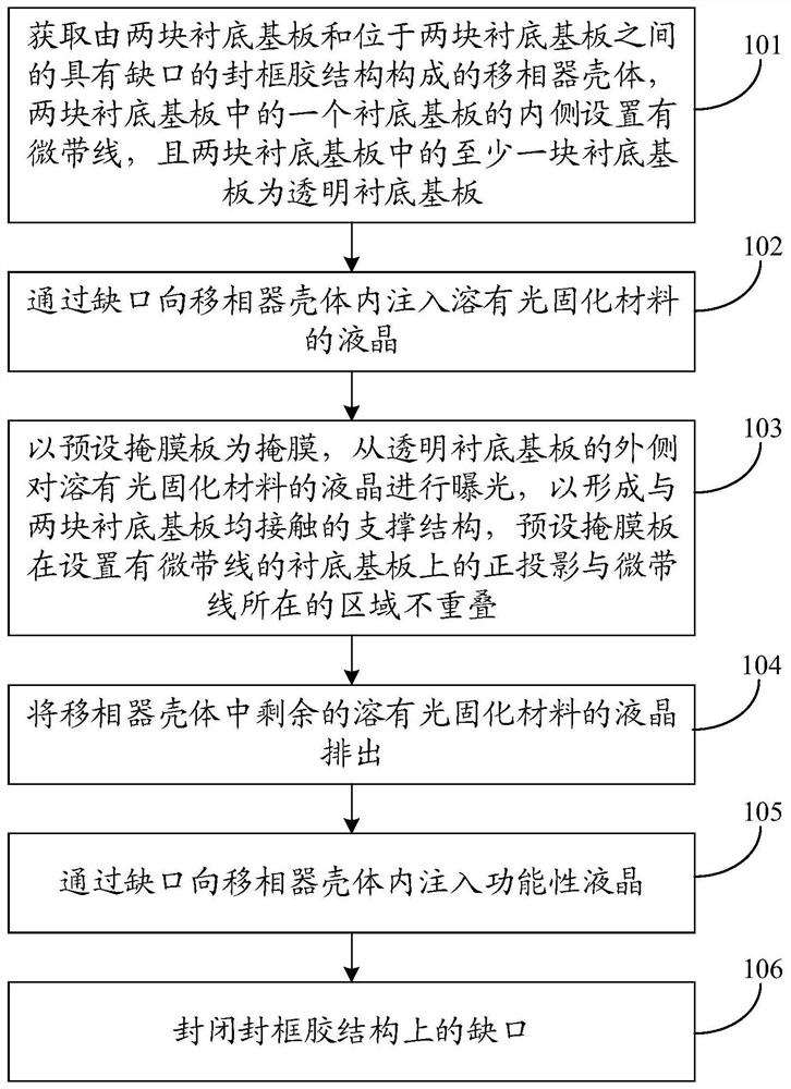
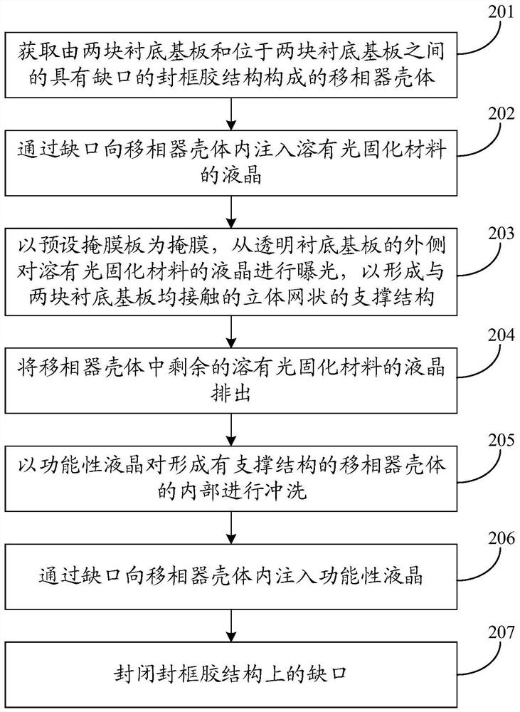
The invention discloses a method for manufacturing a liquid crystal phase shifter and the liquid crystal phase shifter and belongs to the technical field of electronics. The method includes the stepsof acquiring a phase shifter housing; injecting a liquid crystal in which a photocurable material is dissolved into the phase shifter housing through a notch; using a preset mask plate as a mask and exposing the liquid crystal in which the photocurable material is dissolved from the outer sides of transparent substrate base plates to form a stereoscopic network-shaped supporting structure which isin contact with the two substrate base plates; discharging the remaining liquid crystal in which the photocurable material is dissolved in the phase shifter housing; injecting a functional liquid crystal into the phase shifter housing through the notch. Firstly, the liquid crystal in which the photocurable material is dissolved is injected into a phase shifter housing, and then the supporting structure is formed by exposing the liquid crystal in which the photocurable material is dissolved, and finally, the supporting structure maintains the box thickness of the phase shifter, so that friction between the liquid crystal and the substrate base plates is avoided, and the problem that the service life of liquid crystal phase shifters in related technologies is low can be solved. The effect of improving the service life of the liquid crystal phase shifter is achieved.

Description

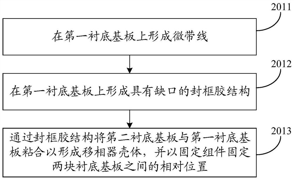
technical field [0001] The invention relates to the field of electronic technology, in particular to a method for manufacturing a liquid crystal phase shifter and the liquid crystal phase shifter. Background technique [0002] A liquid crystal phase shifter is a device used to adjust the phase of electromagnetic waves. It can be used in devices such as radars and accelerators. [0003] A manufacturing method of a liquid crystal phase shifter in the related art includes: 1. Forming a microstrip line and a sealant structure with gaps on the first base substrate, and the sealant structure is provided with a structure for maintaining the liquid crystal. The thickness of the sphere of the phase shifter; 2. Bond the first base substrate and the second base substrate through the sealing glue structure to obtain the phase shifter shell; 3. According to the frequency of the electromagnetic wave to be adjusted by the phase shifter High and low, inject the corresponding functional li...

Claims


Application Information

Patent Timeline
Patent Type & Authority Patents(China)
IPC IPC(8): G02F1/1333G02F1/1341G02F1/1339G02F1/1334
CPCG02F1/1333G02F1/1334G02F1/1339G02F1/1341G02F1/13345
Inventor 张鹏举李锐刘明星朱红赵雨
Owner BOE TECH GRP CO LTD
Learn More