
A Method for Analyzing the Vibration Environment of Sensing Part of Engine and Determining Test Load

A determination method and engine technology, applied in computer-aided design, design optimization/simulation, calculation, etc., can solve the problems of high design and production costs, low service life, etc., to make up for unscientific, improve reliability and economy , good versatility and practical effect

Active Publication Date: 2021-09-28
AECC AVIATION POWER CO LTD
View PDF5 Cites 0 Cited by
  • Summary
  • Abstract
  • Description
  • Claims
  • Application Information

AI Technical Summary

Problems solved by technology

From the scientific research stage to the mass production of an engine, a large number of temperature and pressure test sensing parts are required, especially in the scientific research and trial run stage, and the design and production costs of the sensing part are very high. In order to reduce the use cost of the sensing part, The sensing part must be given a reasonable service life, and none of the current various standards can be directly used in the life test of the sensing part of the aero-engine. The life of the sensing part is very conservative, far lower than similar foreign products service life

Method used

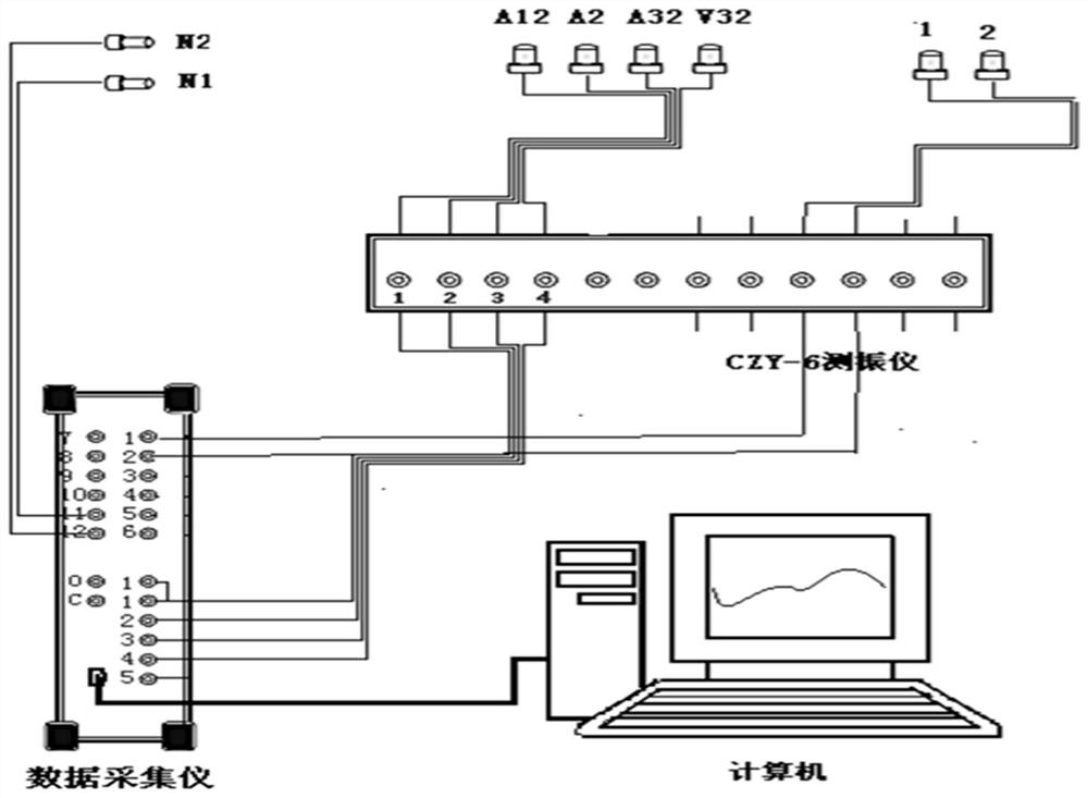
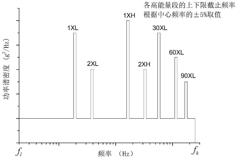
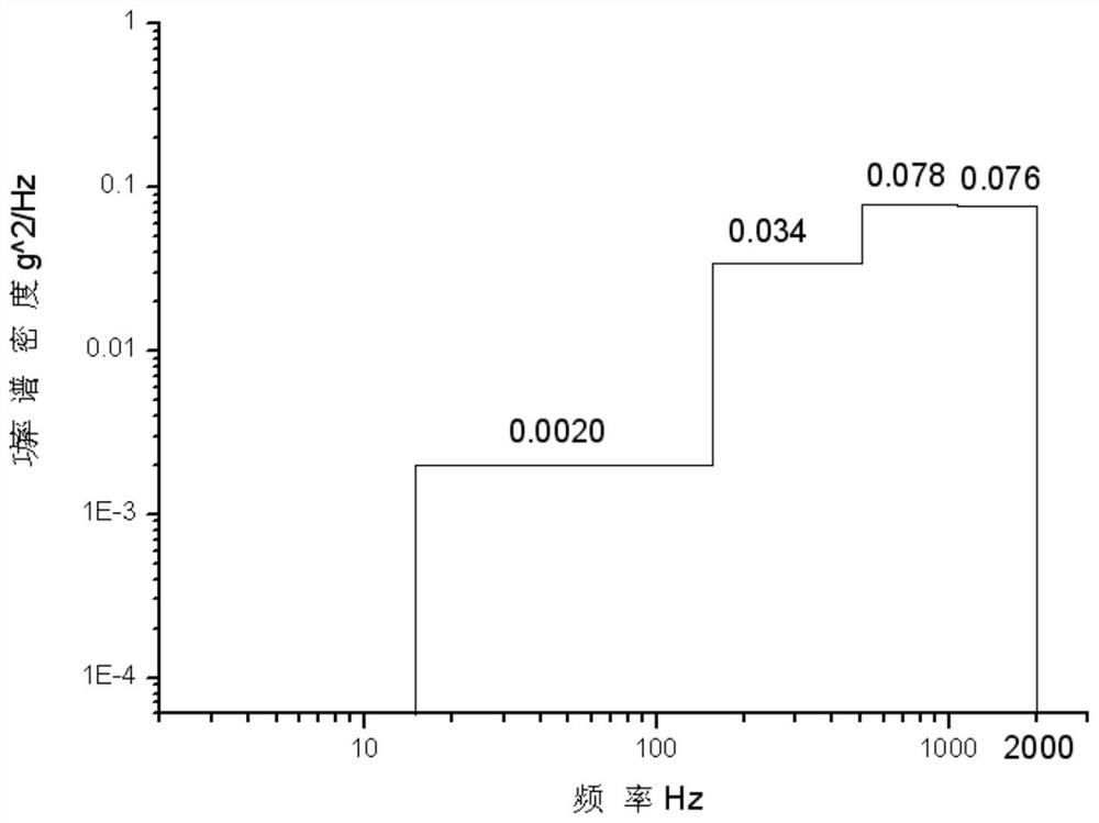

Image

  • A Method for Analyzing the Vibration Environment of Sensing Part of Engine and Determining Test Load
  • A Method for Analyzing the Vibration Environment of Sensing Part of Engine and Determining Test Load
  • A Method for Analyzing the Vibration Environment of Sensing Part of Engine and Determining Test Load

Examples


Embodiment Construction

[0023] The present invention will be described in further detail below in conjunction with the accompanying drawings.

[0024] The method for analyzing the vibration environment of the sensing part of the engine and determining the test load of the present invention comprises the following steps:

[0025] 1. Calculate and analyze the static strength and fatigue strength of the affected part. According to the design requirements of the sensing part and the temperature and pressure parameters of the installation part, the maximum stress and the maximum stress position of the sensing part are calculated by establishing the calculation model of the sensing part and the constraint conditions of the sensing part by using the finite element calculation method. At the same time, according to the rotational speed of the engine in each state, the excitation frequency margin of the natural frequency of each order in each state of the sensing part is calculated, and the resonance point is...


PUM


Abstract

A method for analyzing the vibration environment of a sensing part of an engine and determining a test load, comprising: step 1, calculating and analyzing the static strength and fatigue strength of the sensing part; step 2, selecting a vibration sensor whose temperature resistance and frequency range meet the working environment of the engine , install the vibration sensor on the part of the engine that can reflect the maximum vibration response of the sensing part, and obtain the vibration load data; Step 3, analysis and statistical processing of the test load of the sensing part; Step 4, determination and synthesis of the test profile of the sensing part and simplification; step five, correct the test load in combination with the vibration environment changes of the engine in the field use process; step six, formulate the fatigue test load spectrum according to the corrected test load, select the test section of the sensing part to carry out the fatigue test, And based on the test results, the safe life of the sensing part is given to guide the design and modification of the sensing part. The invention can scientifically and reasonably determine the safe life of the product, and improve the reliability and economy of the product.

Description

technical field [0001] The invention belongs to aero-engine testing technology, in particular to a method for analyzing the vibration environment of an engine sensing part and determining a test load, and proposes a product life evaluation scheme suitable for the sensing part, thereby giving the safe life of the sensing part. Background technique [0002] The sensing part of an aero-engine is an important component for measuring parameters such as temperature and pressure at different cross-sectional positions of the engine. Since most sensing parts are directly inserted into the engine from the engine casing and work in a cantilever state, the reliability of the sensing part is particularly Important, especially the sensing part installed in the main channel of the engine, its reliability directly affects the safety of the engine test run. From the scientific research stage to the mass production of an engine, a large number of temperature and pressure test sensing parts ar...

Claims


Application Information

Patent Timeline
Patent Type & Authority Patents(China)
IPC IPC(8): G06F30/23G06F119/04
CPCG06F30/23G06F2119/04
Inventor 田慧清张瑾刘忠华刘海年张振宇闫庆安于杰郭文涛
Owner AECC AVIATION POWER CO LTD
Learn More