Vector diffraction theory-based Fresnel diffraction optical system imaging simulation method

A technology of Fresnel diffraction and optical system, which is applied in the imaging simulation of Fresnel diffraction optical system based on vector diffraction theory, and in the field of imaging of Fresnel diffraction optical system, which can solve image quality degradation and image quality degradation of diffraction imaging system The mechanism, simulation model and method are rarely reported, and the signal-to-noise ratio of the image transfer function is low, so as to achieve the effect of low SNR

Inactive Publication Date: 2018-08-03
HARBIN INST OF TECH
View PDF2 Cites 2 Cited by
  • Summary
  • Abstract
  • Description
  • Claims
  • Application Information

AI Technical Summary

Problems solved by technology

With the continuous improvement of space resolution requirements for high-orbit surveillance, there is an urgent need for space optical payloads to have the characteristics of super large aperture, light weight, short processing cycle, and low cost. Traditional reflective or refractive imaging systems can no longer fully meet these requirements. Requirements, and diffractive optical imaging technology can overcome this limitation, so it is urgent to study the simulation model and method of imaging quality for optical diffractive imaging system
However, according to the existing literature, most of the research in this area is aimed at reflective or refractive systems, and there are few reports on the image quality degradation mechanism, simulation models and methods of diffractive imaging systems.
Compared with the traditional payload, the image quality degradation of the diffractive optical imaging system is more serious, and the transfer function (MTF) and signal-to-noise ratio (SNR) of the image are lower, especially the point spread function (PSF) at different fields of view. The large spatial variability clearly cannot be simulated with traditional reflective or refractive system models

Method used


Image

  • Vector diffraction theory-based Fresnel diffraction optical system imaging simulation method
  • Vector diffraction theory-based Fresnel diffraction optical system imaging simulation method
  • Vector diffraction theory-based Fresnel diffraction optical system imaging simulation method

Examples


Embodiment Construction

[0027] The technical solution of the present invention will be further described below in conjunction with the accompanying drawings, but it is not limited thereto. Any modification or equivalent replacement of the technical solution of the present invention without departing from the spirit and scope of the technical solution of the present invention should be covered by the present invention. within the scope of protection.

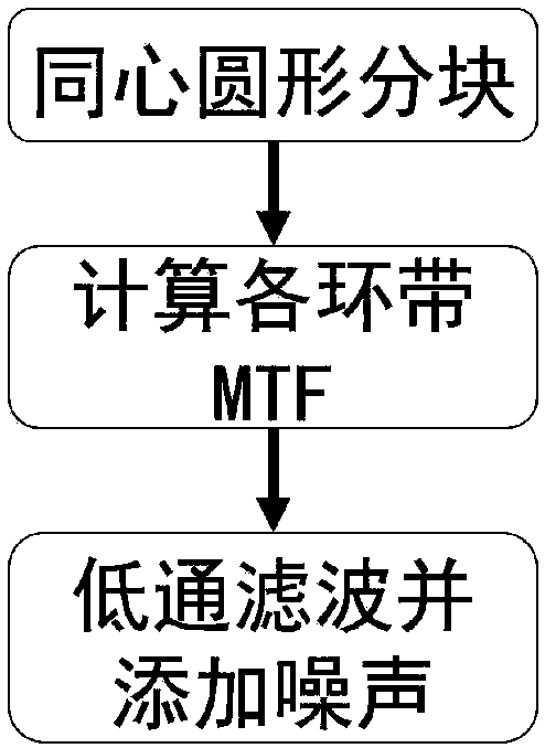
[0028] The invention provides a Fresnel diffractive optical system imaging simulation method based on vector diffraction theory, such as figure 1 As shown, the specific implementation steps of the method are as follows:
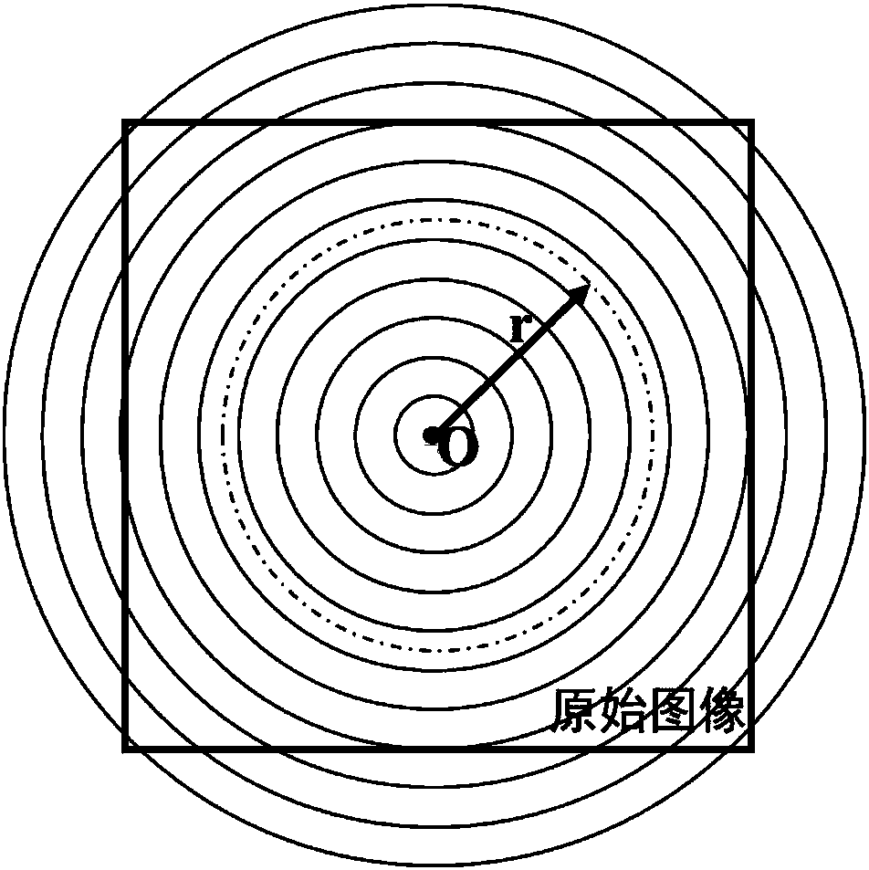
[0029] Step 1: Based on the idea of ​​concentric circular blocks, the original image is divided into several annular image blocks with the same annular width. Specific steps are as follows:

[0030] (1) Based on the idea of ​​concentric circular blocks, the original image is divided into several annular image blocks with the same rin...


PUM


Abstract

The invention discloses a vector diffraction theory-based Fresnel diffraction optical system imaging simulation method. The method comprises the following steps of: 1, segmenting an original image into a plurality of ring image blocks with same ring widths on the basis of a concentric circle blocking thought; 2, calculating an MTF of each ring by utilizing a time domain finite difference method (FDTD); and 3, carrying out low-pass filter on the image blocks by utilizing the MTF of each ring, and adding noise. The method is suitable for simulating and estimating imaging quality of optical systems which take diffraction mirrors as main mirrors, and is capable of obtaining simulated images with diffraction optical characteristics such as low MTF, low SNR, large-size PSF space shift change, providing support for optimum design of diffraction optical systems and research and verification of image processing algorithms, and filling the gaps of current diffraction optical imaging quality finesimulation modeling theoretical methods.

Description

technical field [0001] The invention belongs to the technical field of optical imaging simulation, and in particular relates to an imaging method of a Fresnel diffractive optical system, in particular to an imaging simulation method of a Fresnel diffractive optical system based on vector diffraction theory. Background technique [0002] The simulation estimation of optical remote sensing imaging quality has important guiding significance and application value in the prediction of remote sensing tasks such as reconnaissance, surveying and mapping, surveillance, imaging system optimization design and performance evaluation, and image processing algorithm verification. With the continuous improvement of space resolution requirements for high-orbit surveillance, there is an urgent need for space optical payloads to have the characteristics of super large aperture, light weight, short processing cycle, and low cost. Traditional reflective or refractive imaging systems can no longe...

Claims


Application Information

Patent Timeline
Patent Type & Authority Applications(China)
IPC IPC(8): G06T1/00G06T5/00
CPCG06T1/0007G06T5/002
Inventor 智喜洋李允巩晋南张伟江世凯王达伟
Owner HARBIN INST OF TECH
Why Eureka
Try Eureka