
System for determining fill level

A filling level, fuel tank technology, applied in the layout, instrumentation, liquid/fluid solid measurement, etc. combined with the fuel supply of the internal combustion engine, can solve the problems of failure, cost, etc., and achieve the effect of low cost and accurate measurement results

Active Publication Date: 2021-06-01
VTESCO TECH GMBH
View PDF5 Cites 0 Cited by
  • Summary
  • Abstract
  • Description
  • Claims
  • Application Information

AI Technical Summary

Problems solved by technology

These systems include many components that require cost, can fail, and introduce additional weight into the box or box system

Method used


Image

  • System for determining fill level
  • System for determining fill level
  • System for determining fill level

Examples


Embodiment Construction

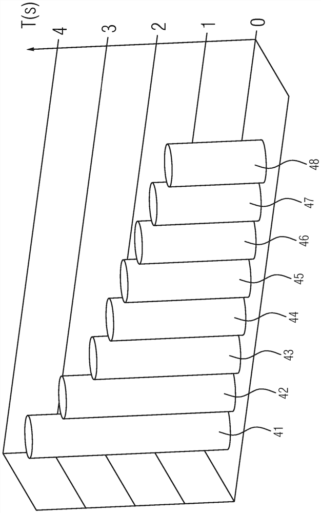
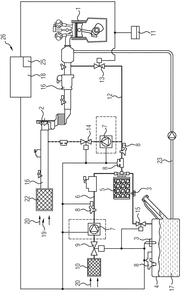
[0015]figure 1 An internal combustion engine 1 is shown. The internal combustion engine 1 is supplied to fresh air 20 via the intake line 16. The fresh air 20 is guided from the fresh air side 19 through the air filter 22 to the intake line 16, and may be compressed by means of exhaust turbocharger 2 or supercharger, and then supplied to internal combustion engine 1 Combustion chamber. Further, the internal combustion engine 1 is supplied with fuel 17 from the fuel tank 4 via the fuel line 23.figure 1 Furthermore, a fuel tank system 26 having a fuel tank 4 and a battery element 5 for temporarily storeing a hydrocarbon is exhibited. The fuel tank 4 and the battery element 5 are connected to each other such that the hydrocarbon from the fuel 17 located in the fuel tank 4 can be stored in the battery element 5. The battery element 5 can, for example, be formed as an active carbon storage battery. The activated carbon battery is a kanister, wherein carbon is arranged such that the hydro...


PUM


Abstract

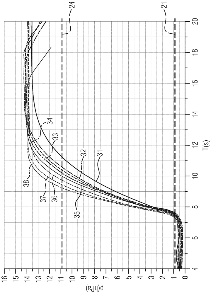
The invention relates to a system for determining the fill level of fuel located in a fuel tank. To specify an inexpensive system for determining the fill level of fuel located in a fuel tank, the system has an electrically driven air pump, at least one valve, a pressure sensor, a control unit and a timing element, wherein the control unit actuates the valve so that The fuel tank is closed in a hermetic manner, and the control unit activates the air pump so that the pressure in the fuel tank increases until an upper threshold is reached, and the timing element determines the time until the pressure has reached the upper threshold, and the fuel located in the fuel tank The fill level is determined from the time it takes to reach the upper threshold.

Description

Technical field[0001]The present invention relates to a system for determining a fill level of fuel located in a fuel tank.Background technique[0002]Many measures have been introduced in the past few decades in recent decades in recent decades. One of these measures is to use a fuel tank system, wherein the fuel tank is coupled to a battery element for temporarily storeing hydrocarbons. The hydrocarbon produced from the fuel is escaped from the fuel, where the hydrocarbon is brought into gas in the air, and it is intended to make the hydrocarbon do not enter the atmosphere. In the case where there is a high temperature or when traveling on an uneven floor, the hydrocarbon is also increased from the fuel, wherein the hydrocarbon must be effectively ensured that the hydrocarbon does not escape from the atmosphere. . In particular, in the case where the mixed power vehicle is completely downtown, it is necessary to temporarily store a hydrocarbon having a gas escape in an effective man...

Claims


Application Information

Patent Timeline
Patent Type & Authority Patents(China)
IPC IPC(8): B60K15/03G01F23/14
CPCB60K15/03G01F22/02G01F23/14B60K2015/03361
Inventor M.魏格尔H.许勒L.查姆帕
Owner VTESCO TECH GMBH
Learn More