Exhaust gas after-treatment arrangement and method for operating such an arrangement

A technology for exhaust post-treatment and exhaust pipes, which is applied in exhaust treatment, exhaust devices, machines/engines, etc. It can solve problems such as high back pressure, high fuel consumption, and the size of the catalytic converter cannot be designed to achieve good reliability. The effect of control and adjustability

Inactive Publication Date: 2018-08-03
CONTINENTAL AUTOMOTIVE GMBH
View PDF5 Cites 0 Cited by
  • Summary
  • Abstract
  • Description
  • Claims
  • Application Information

AI Technical Summary

Problems solved by technology

In order to avoid insufficient heating of the catalytic converter at low exhaust gas flow - which would have a negative effect on the catalytic reaction - the catalytic converter must not be dimensioned for the maximum occurring exhaust gas flow
This in turn leads to the disadvantage that high counterpressures are generated at higher exhaust gas flows
Higher backpressure leads to an undesired reduction in engine power and to higher fuel consumption

Method used


Image

  • Exhaust gas after-treatment arrangement and method for operating such an arrangement
  • Exhaust gas after-treatment arrangement and method for operating such an arrangement
  • Exhaust gas after-treatment arrangement and method for operating such an arrangement

Examples


Embodiment Construction

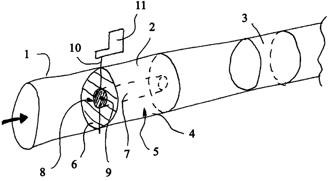
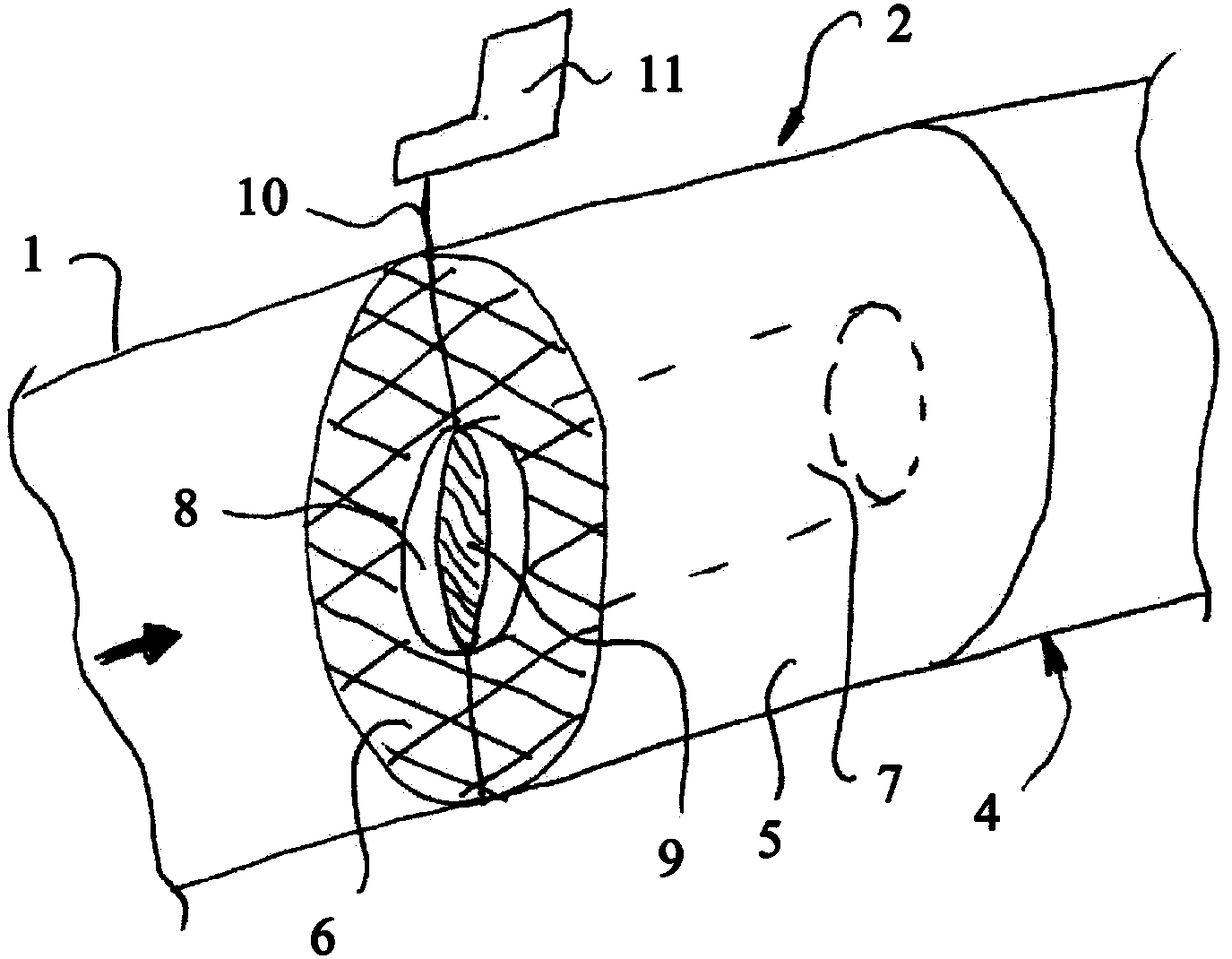
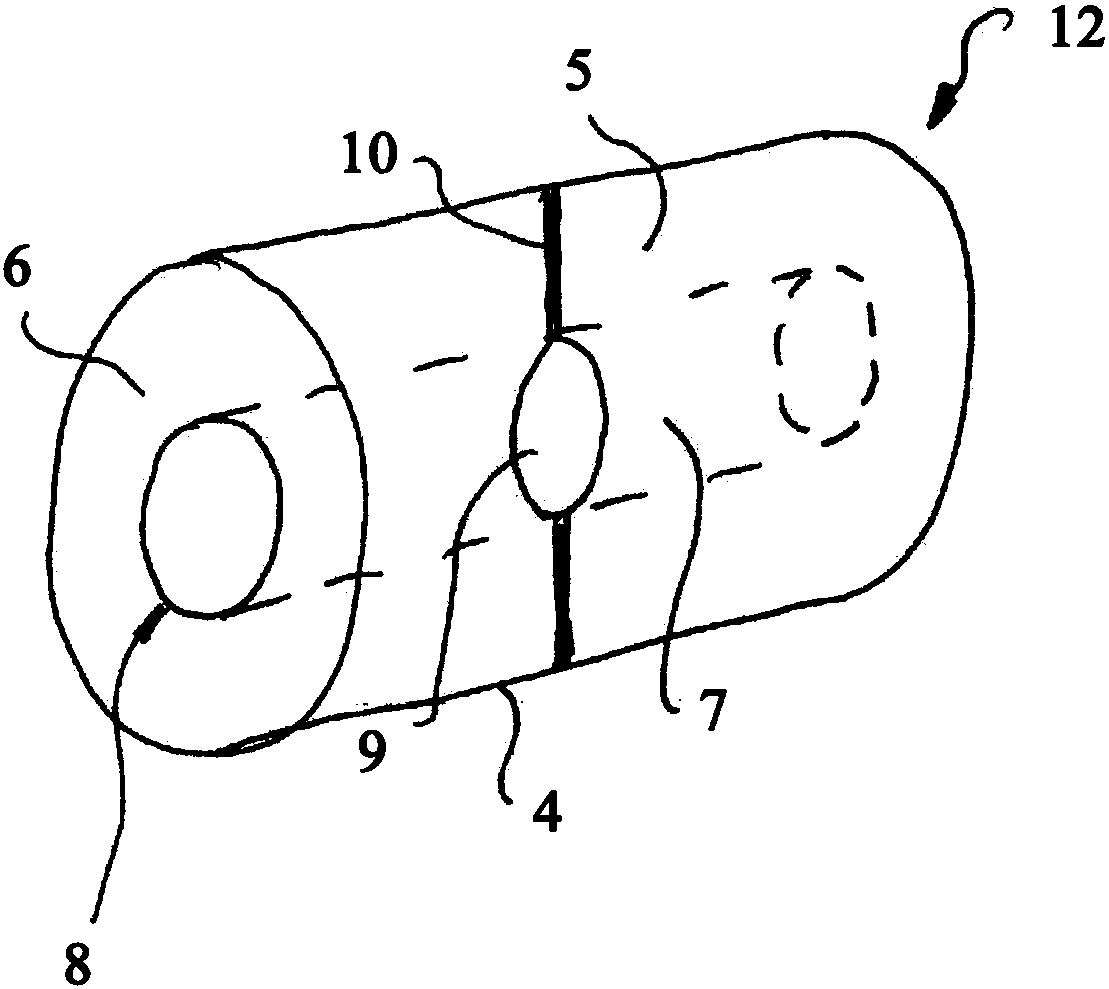
[0032] figure 1A section of an exhaust gas line 1 is shown, in which a catalytic converter is arranged as an exhaust gas aftertreatment device 2 . A further exhaust-gas aftertreatment device 3 , which is also designed as a catalytic converter, is arranged downstream of the catalytic converter 2 . The catalytic converter 2 has a housing 4 which surrounds a honeycomb body 5 . The honeycomb body 5 is formed from a plurality of laminates which form the catalytic converter body 6 and are overflow surfaces for the exhaust gas, wherein catalytic reactions take place in the flowing exhaust gas when flowing through the catalytic converter body 6 . Along its longitudinal axis, the honeycomb body 5 has a central cell 7 through which the exhaust gas can flow while avoiding the catalytic converter base body 6 . The main flow direction of the exhaust gas is indicated by arrows. A movable element 9 is provided on the inlet 8 of the duct 7 , which blocks the inlet 8 in the illustration sho...


PUM


Abstract

The invention relates to an exhaust gas after-treatment arrangement comprising an exhaust gas pipe (1) and at least one exhaust gas after-treatment device (2) which has a honeycomb body (5) forming aflow surface for the exhaust gas. The honeycomb body (5) is a hollow cylinder having a central channel (7), wherein one movable element (9, 15) is arranged such that the movable element can be moved between two end positions, wherein in the first end position a larger cross-section of the channel (7) is opened than in the second end position.

Description

technical field [0001] The invention relates to an exhaust gas aftertreatment system and a method for operating an exhaust gas aftertreatment system with an exhaust gas line and at least one exhaust gas aftertreatment device, the at least one exhaust gas aftertreatment device The treatment device has a honeycomb body which forms an overflow surface for the exhaust gas. Background technique [0002] Such exhaust gas aftertreatment devices with honeycomb bodies are known as catalytic converters for exhaust gas aftertreatment. The catalytic converter usually has a housing which on the one hand surrounds the honeycomb body and on the other hand is connected to the exhaust gas line. The operating temperature required for the catalytic reaction is usually provided by the exhaust gas, which, when flowing through the catalytic converter, partly conveys its temperature to the catalytic converter and thereby heats the catalytic converter. In an attempt to optimize the catalytic conv...

Claims


Application Information

Patent Timeline
Patent Type & Authority Applications(China)
IPC IPC(8): F01N3/022F01N3/20F01N3/28
CPCF01N3/0222F01N3/2053F01N3/2828F01N3/2892F01N2240/36F01N2410/02F01N2410/10Y02T10/12
Inventor O·霍尔兹
Owner CONTINENTAL AUTOMOTIVE GMBH
Why Eureka
Try Eureka