Rotary damper

A rotary damper and damper technology, applied in non-rotational vibration suppression, shock absorber, shock absorber, etc., can solve the problems of unsuitable multi-functional rotary damper and the inability to realize economical realization of high-pressure end side seals of gears, etc. achieve simple structure and effect

Active Publication Date: 2018-08-03
INVENTUS ENG
View PDF11 Cites 13 Cited by
  • Summary
  • Abstract
  • Description
  • Claims
  • Application Information

AI Technical Summary

Problems solved by technology

High-pressure end-side sealing of complexly formed gears used in combination with ferrous fluids cannot be realized economically in high-volume production
Therefore, the construction prin...

Method used


Image

  • Rotary damper
  • Rotary damper
  • Rotary damper

Examples


Embodiment Construction

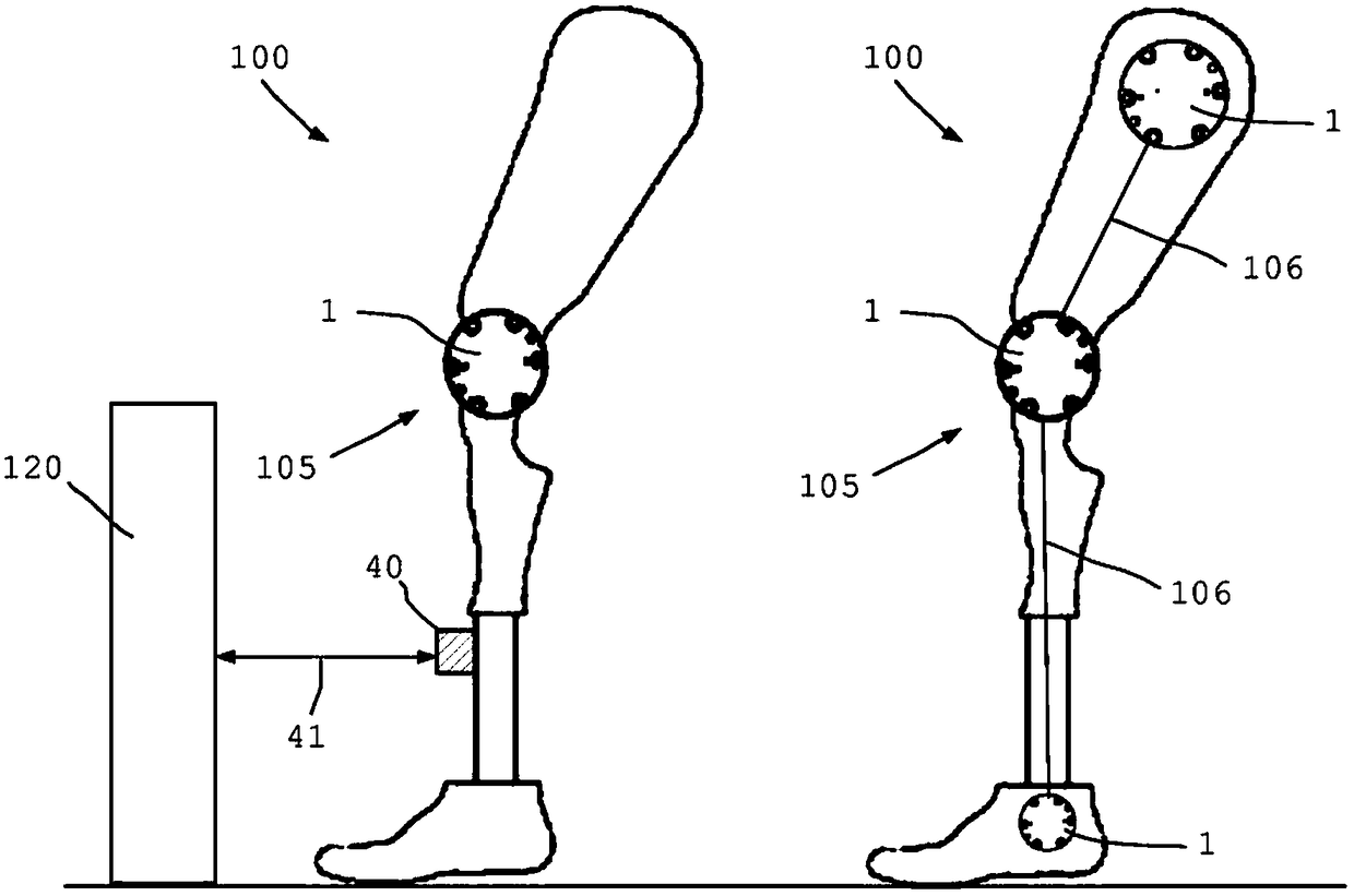
[0124] figure 1 The use of the rotary damper 1 according to the invention as device 100 on a prosthesis 105 is shown. The prosthesis 105 shown in the left half depicts use on the knee joint where the rotational damper 1 dampens the rotational movement between the thigh and the calf.

[0125] The rotary damper 1 can also be controlled by means of sensor data from a sensor device 40 which, for example, detects a distance 41 to an object 120 . For example, if during a climbing step the distance and height of successive steps are detected by such a sensor device 40 , the rotary damper 1 can be targeted with the following requirements.

[0126] figure 1 The right half of FIG. 1 shows a leg prosthesis as prosthesis 105 , wherein three rotational dampers 1 are provided here, namely one at the ankle, one at the knee and one at the hip joint. The three rotary dampers 1 are connected together via one or more fluid and control lines 106 such that hydraulic interaction between the indi...


PUM


Abstract

The invention relates to a rotary damper having a displacer device, said displacer device comprising a damper shaft (3) and displacer components (4, 5) engaging into one another, wherein a rotationalmovement of the damper shaft (3) can be damped. The displacer device contains a magnetorheological fluid as a working fluid. A magnetic field (10) of a magnetic field source having an electric coil (9) can be controlled by means of an associated control device. An end-side axial gap (25) is formed between the housing and the displacer device. An essential part of the magnetic field (10) of the magnetic field source passes through the axial gap (25) between the housing and the displacer components (4, 5). The magnetorheological fluid can be influenced by the magnetic field (10) in order to adjust a damping of the rotational movement of the damper shaft (3). The magnetic field (10) also causes a seal of the end-side axial gap (25).

Description

technical field [0001] The present invention relates to a rotary damper, wherein the rotary damper has at least one displacement device with a damper shaft and a displacement member which engages and rotates with each other to damp the rotational movement of the damper shaft. Background technique [0002] In the prior art, various rotary dampers or rotary dampers or rotary brakes are known, with which the rotary movement of the damper shaft can be damped. However, known rotary dampers are generally not multifunctional, or the required braking torque is too small, the rotational speed is too high or the braking torque cannot be changed or set, or not fast enough. [0003] DE 10 2013 203 331 A1 discloses a rotary damper for a vehicle for damping relative movements between a wheel and a vehicle superstructure. The transmission stage has a plurality of gearwheels in operative connection. The rotational movement of the gears can deliver hydraulic medium for hydraulic damping. ...

Claims


Application Information

Patent Timeline
IPC IPC(8): F16F9/53F16F9/12
CPCF16F9/12F16F9/535
Inventor S·巴特洛格
Owner INVENTUS ENG
Why Eureka
Try Eureka