Infrared sensor device

An infrared sensor, infrared technology, applied in measuring devices, instruments, scientific instruments, etc., can solve the problems of increased heat capacity, volume, and heat capacity of light guides, and achieve high measurement directivity, reduced heat capacity, and high thermal response. sexual effect

Inactive Publication Date: 2018-08-03
MITSUBISHI MATERIALS CORP
View PDF7 Cites 3 Cited by
  • Summary
  • Abstract
  • Description
  • Claims
  • Application Information

AI Technical Summary

Problems solved by technology

[0010] That is, in the technique of Patent Document 1, there is a problem that the thickness of the thick-walled light guide is changed to form a tapered light guide path, but the portion of the infrared sensor close to the light guide path becomes thicker and the volume increases, resulting in a The heat capacity of the optical device increases, and the radiation and heat conduction from the light guide path greatly affect the sensitivity and accuracy of the infrared sensor
[0011] In addition, in the technique of Patent Document 2, since the through hole as the light guide path is formed on the substantially rectangular parallelepiped frame, the heat capacity becomes larger along with the large volume of the frame itself as the light guide path member. Radiation and heat conduction greatly affect the sensitivity and accuracy of infrared sensors
[0012] Furthermore, in the technology of Patent Document 3, the guide cylinder for controlling the infrared light reaching the light receiving surface is formed of a thin material, but the guide cylinder has a gradient inclined inward, and has a substantially trapezoidal shape in which the inner diameter of the upper opening side is reduced. In order to guide the desired infrared light to the light-receiving surface in the guide cylinder, the size of the light guide may increase

Method used


Image

  • Infrared sensor device
  • Infrared sensor device
  • Infrared sensor device

Examples


Embodiment Construction

[0037] Below, refer to Figure 1 to Figure 4 A first embodiment of the infrared sensor device according to the present invention will be described.

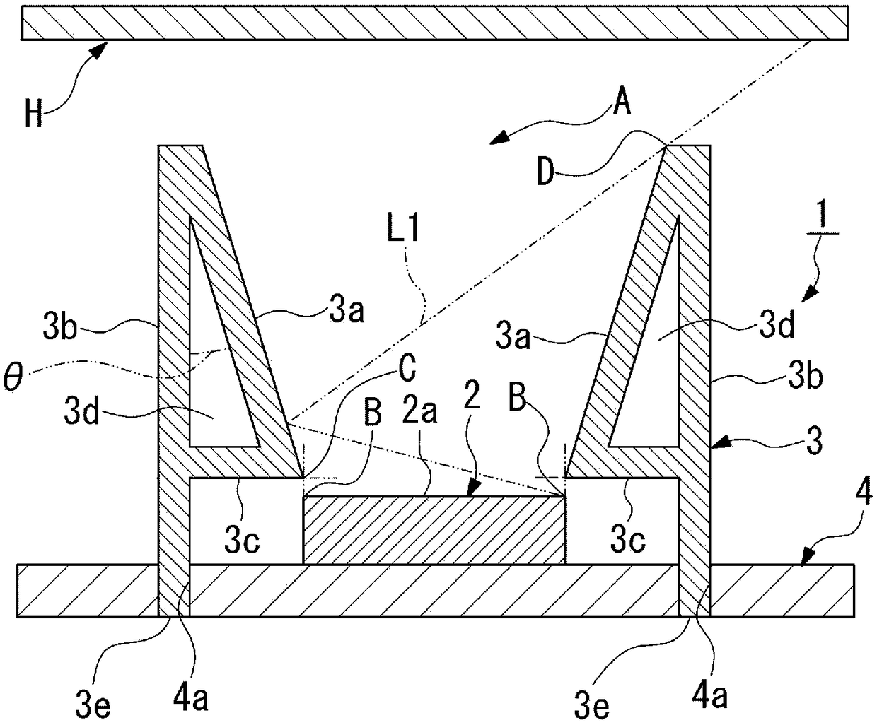
[0038] Such as figure 1 As shown, the infrared sensor device 1 of the present embodiment measures, for example, the temperature of a fixing roller of toner, and a measuring object H such as a fixing roller is provided toward the opening A.

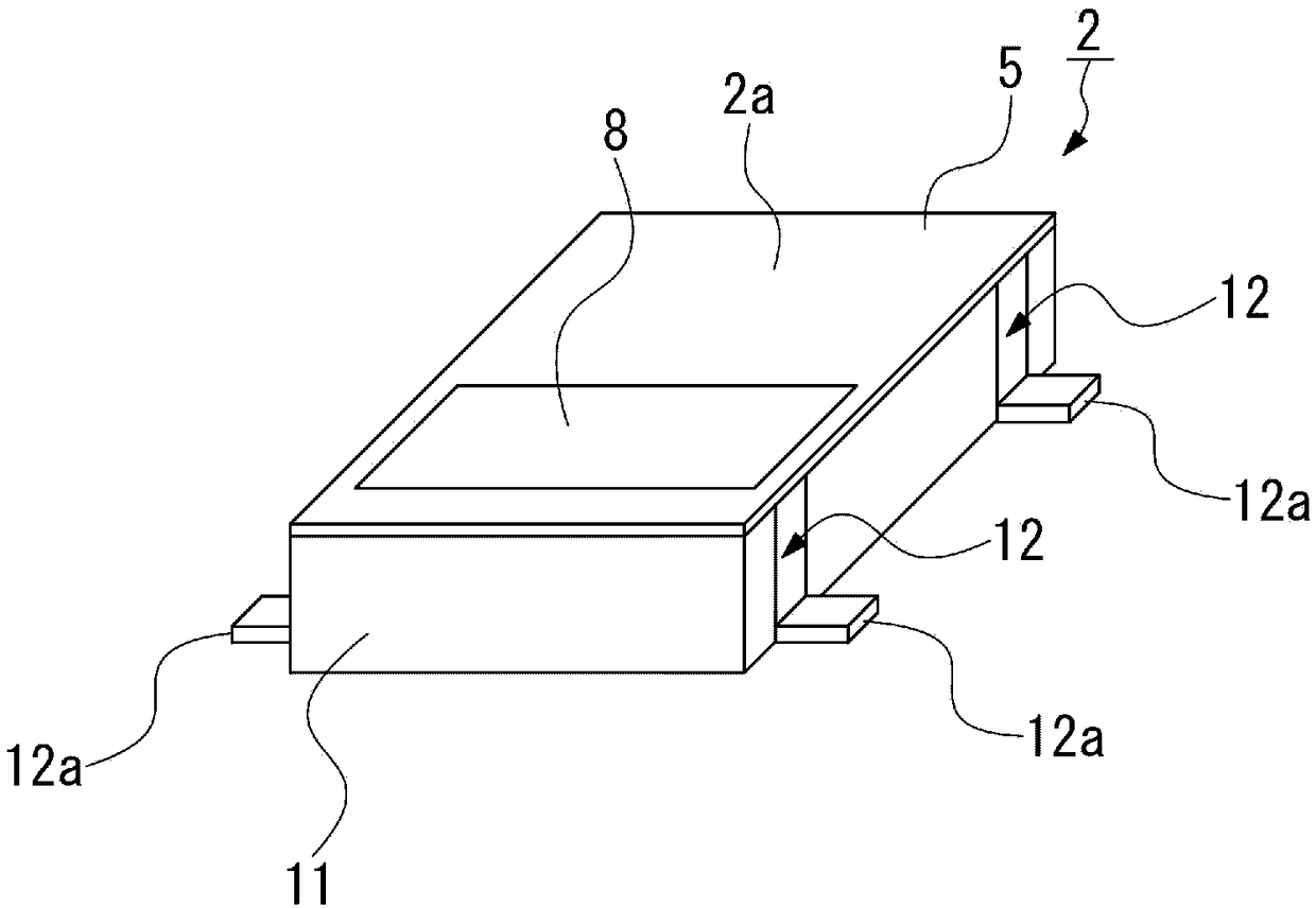
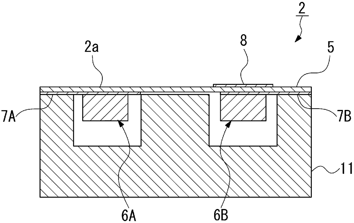
[0039] This infrared sensor device 1 is provided with an infrared sensor main body 2, a cylindrical light guide member 3 provided around at least the light receiving surface 2a of the infrared sensor main body 2 and having an opening A directly above the light receiving surface 2a, and an infrared sensor main body provided with 2 and the substrate 4 of the light guide path component 3. In addition, in figure 1 In , the infrared sensor main body 2 is schematically shown.

[0040]The light guide member 3 is formed of a plate, and at least one of the surfaces surrounding the light receiving ...


PUM


Abstract

Provided is a small-sized infrared sensor device which is capable of measuring temperatures with high accuracy, and wherein a light guide path member has a low heat capacity. An infrared sensor deviceaccording to the present invention is provided with: an infrared sensor main body; and a light guide path member that is arranged so as to surround at least a light receiving surface of the infraredsensor main body and has an opening positioned immediately above the light receiving surface. The light guide path member is formed of a plate material, and at least one surface among the surfaces that surround the light receiving surface is formed as an infrared light reflecting surface that is configured from an inclined plate part wherein the light receiving surface-side surface is inclined toward the opening.

Description

technical field [0001] The present invention relates to an infrared sensor device that detects infrared rays from an object to be measured such as a fixing roller of toner and measures the temperature of the object to be measured. Background technique [0002] Conventionally, an infrared sensor has been used as a temperature sensor that measures the temperature of the object to be measured by non-contact detecting infrared rays radiated from the object to be measured. Such an infrared sensor is used in various fields such as measuring the temperature of a fixing roller of toner (developer) built in copiers, printers, etc., and indoor temperature control of air conditioners. [0003] For example, Patent Document 1 describes a non-contact temperature measurement sensor including an infrared sensor, an optical lens, and a light guide. The light guide for the non-contact temperature sensor is provided on the frame so as to guide infrared rays to the optical lens provided on the...

Claims


Application Information

Patent Timeline
Patent Type & Authority Applications(China)
IPC IPC(8): G01J1/06G01J1/02
CPCG01J5/0815G01J5/06G01J5/0808G01J5/07G01J1/02G01J1/06G01J5/04G01J5/08
Inventor 平野晋吾田里和义细川雄亮中村贤藏西山雅史中村健治四元孝二小林功樋口由浩
Owner MITSUBISHI MATERIALS CORP
Why Eureka
Try Eureka