Film coating equipment used in plaster production, and application method thereof
A technology of coating and plaster, which is applied to the device and coating of the surface coating liquid, which can solve the problems of adverse effects on workers' health, low production efficiency, difficult control of spreading area and thickness, etc.
- Summary
- Abstract
- Description
- Claims
- Application Information
AI Technical Summary
Problems solved by technology
Method used
Image
Examples
Embodiment 1
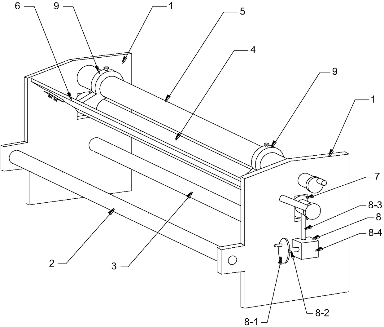
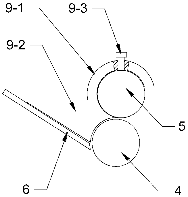
[0045] See attached figure 1 , a kind of coating laminating equipment for producing plaster, comprises frame, first guide roller 2, second guide roller 3, gluing lower roller 4, gluing upper scraping roller 5, discharge plate 6.
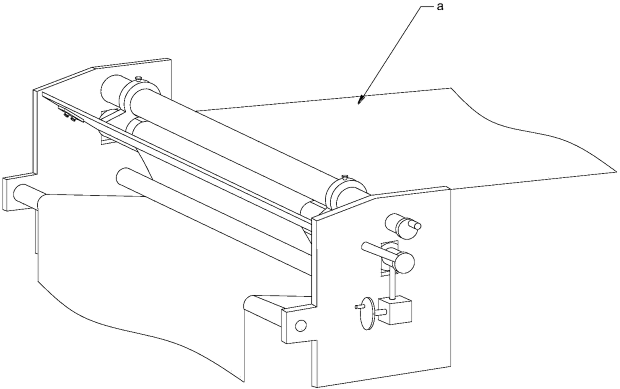
[0046] The frame includes two side plates 1 vertically parallel to the left and right, the first guide roller 2, the second guide roller 3, the glued lower roller 4, the glued upper scraping roller 5 and the discharge plate 6 are all horizontal Installed between two side panels. Wherein, the first guide roller 2 and the second guide roller 3 are rotatably installed and are driven rollers; the upper scraping roller 5 for gluing is arranged above the lower roller 4 for gluing, and the discharge plate 6 is arranged under the gluing The feeding side of the roller 4 and the gluing upper scraping roller 5; there is a gap between the bottom of the discharge plate 6 and the gluing lower roller 4, so that the coating can pass through; further, under the glui...
Embodiment 2
[0052] On the basis of Embodiment 1, further, in order to prevent the glue from leaking from the gap between the discharge plate and the glue lower roller, and to ensure that the coating can pass through the gap smoothly, the two sides of the discharge plate 6 The end is installed on the side plate 1 of the frame through an adjustable mechanism. See attached Figure 5 And attached Figure 6 , a connecting flange 10-1 is arranged on the side plate of the frame, two bolt through holes 10-2 are arranged on the connecting flange, and bolts on the connecting flange are arranged at the side end position of the discharge plate 6 The elongated through hole 10-3 that the through hole matches, the elongated through hole is arranged along the width direction of the discharge plate, realizes the fixing of the discharge plate 6 and the connecting flange 10-1 by the bolt and nut assembly 10-4 (bolts pass through Through the bolt through hole of the connecting flange and the long through h...
Embodiment 3
[0054] See attached Figure 7 , on the basis of Embodiment 1 or Embodiment 2, an electric heating plate 11 is also provided on the back of the discharge plate 6, and the heat of the electric heating plate 11 is transferred to the discharge plate 6, so that the The glue maintains the best viscosity and fluidity, and prevents the glue from curing due to lower temperature, which affects the coating effect.
PUM
 Abstract
Description
Claims
Application Information
 - R&D
- Intellectual Property
- Life Sciences
- Materials
- Tech Scout
- Unparalleled Data Quality
- Higher Quality Content
- 60% Fewer Hallucinations
Browse by: Latest US Patents, China's latest patents, Technical Efficacy Thesaurus, Application Domain, Technology Topic, Popular Technical Reports.
© 2025 PatSnap. All rights reserved.Legal|Privacy policy|Modern Slavery Act Transparency Statement|Sitemap|About US| Contact US: help@patsnap.com


