

Middle driving electric spindle
A technology for driving an electric spindle and an axial direction. It is used in large fixed members, metal processing machinery parts, metal processing equipment, etc. It can solve problems such as unfavorable accuracy and stability, difficulty in forming linkage, and occupying space, so as to reduce replacement costs and reduce costs. The effect of maintenance cost, reduction of transmission loss, and improvement of the scope of application
- Summary
- Abstract
- Description
- Claims
- Application Information
AI Technical Summary
Problems solved by technology
Method used
Image

Examples
Embodiment 1
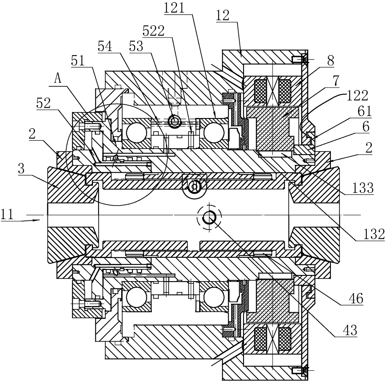
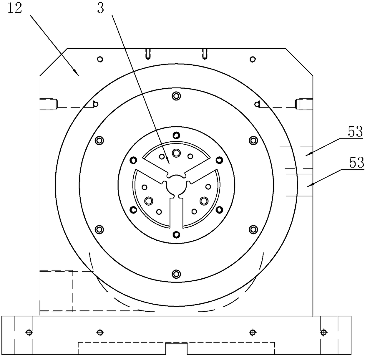
[0039] Embodiment 1: A kind of medium-driven electric spindle, such as figure 1 and image 3 As shown, it includes a shell assembly 1 with a through hole 11, two extension sleeves 2, two ferrules 3 embedded in the extension sleeves 2 for clamping workpieces, a pull sleeve 4 connecting two ferrules 3 and A control structure 5 that drives one of the extension sleeves 2 to move axially. When the extension sleeve 2 moves axially, the two ferrules 3 are forced to shrink.
[0040] The shell assembly 1 includes a box body 12 and a seat cover 13 . The seat cover 13 is arranged in the box body 12 and an angular contact bearing 121 is connected between the box body 12 and the box body 12 . The outer wall of the other end of the seat cover 13 is provided with an annular fastening groove 31 with only one-way side walls. The fastening groove 31 is sleeved with one end and the side wall of the fastening groove 31 abuts against the rotor 7, and the rotor 7 and An anti-rotation key 132 is...
Embodiment 2
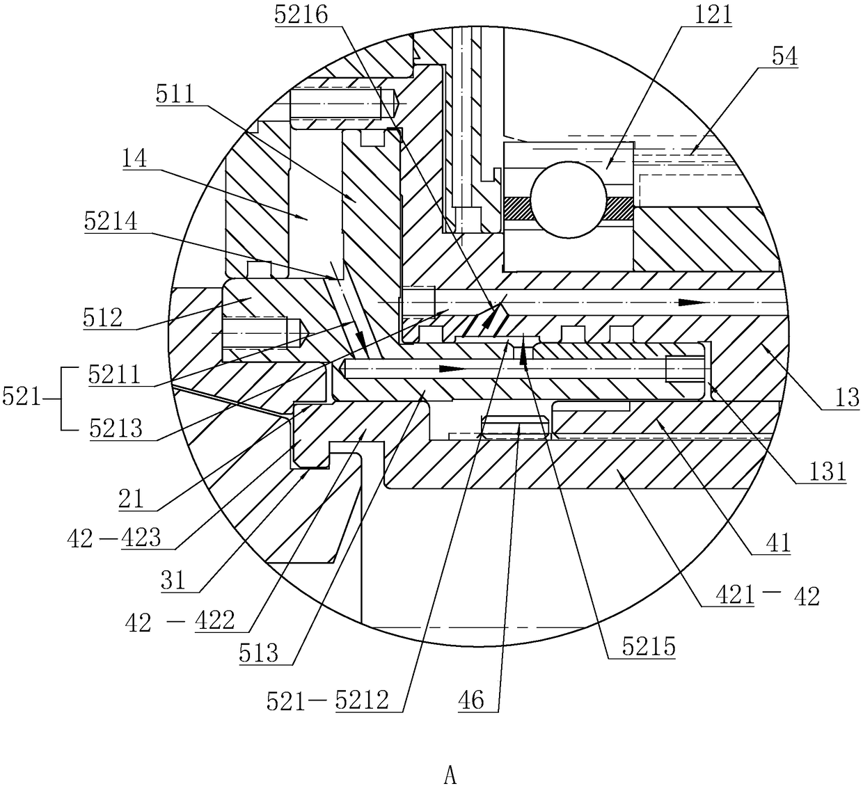
[0049] Embodiment 2: The difference from Embodiment 1 lies in that the structure of the pulling sleeve 4 is different. The pull sleeve 4 includes a left sleeve 44 and a right sleeve 45 with hooks 423 on both ends facing away from each other. The hooks 423 are snapped into the limiting groove 31, and the outer wall of the left sleeve 44 is tightly embedded in the inner wall of the through hole 11. The inner wall of the left sleeve 44 is provided with an accommodating groove 441, and the right sleeve 45 also includes an extension part 421 threadedly connected with the accommodating groove 441 and an external connection part 422 tightly embedded in the inner wall of the through hole 11, and the hook part 423 is arranged on the external connection part 422 On the inner wall; between the outer connecting portion 422 and the left sleeve 44 is provided a locking piece 46 which is threadedly connected to the extension portion 421 and abuts against the left sleeve 44 .
PUM
 Abstract
Description
Claims
Application Information