Electric welding machine equipment

A technology for electric welding machines and equipment, which is applied in the direction of arc welding equipment, welding equipment, metal processing equipment, etc., which can solve the problems of inconvenient maintenance, easy heating of electric welding machines, and the inability of heat dissipation equipment to fully achieve the heat dissipation effect of electric welding machines. The effect of convenience and simple structure

Inactive Publication Date: 2018-08-07
王建刚
View PDF0 Cites 0 Cited by
  • Summary
  • Abstract
  • Description
  • Claims
  • Application Information

AI Technical Summary

Problems solved by technology

[0002] The electric welding machine is used to combine the objects to be contacted. At present, the scope of use is extremely wide. The electric welding machine is generally divided into mobile type or fixed installation on the workbench. The electric welding machine used for fixed installation on the workbench is usually It is troublesome to disassemble, and it is not easy to repair and maintain. Moreover, the electric welding machine is very easy to generate heat when it is in use. The current heat dissipation equipment cannot fully achieve the heat dissipation effect of the electric welding machine. Therefore, there is an urgent need for a welding machine that can quickly dissipate heat and disassemble.

Method used


Image

  • Electric welding machine equipment
  • Electric welding machine equipment
  • Electric welding machine equipment

Examples


Embodiment Construction

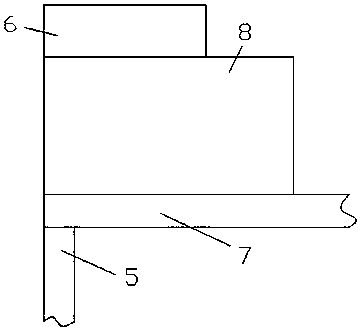
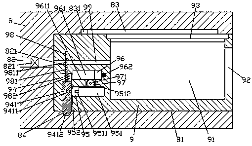
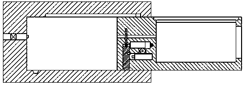
[0015] Such as figure 1 , figure 2 and image 3 As shown, a kind of electric welding machine equipment of the present invention includes a machine cover body 8 fixedly installed on the work surface 7, the bottom of the work surface 7 is provided with a supporting foot column 5, and the top end surface of the machine cover body 8 is fixed with a The heat removal device 6, the right end surface of the cover body 8 is provided with a container 81, the welding body 9 is slidably connected to the container 81, and the inner wall of the cover body 8 on the left side of the container 81 is The body is provided with a gas transmission tube 82 extended from left to right, and the right end of the gas transmission tube 82 is fixed with an insertion port 821 that pushes into the storage tank 81, and the bottom end surface of the storage tank 81 is provided with Slanted hole 84, the top end surface of the right side of the welding body 9 is provided with a placement cavity 91, and the ...


PUM


Abstract

The invention discloses electric welding machine equipment. The electric welding machine equipment comprises a machine cover body which is fixedly installed on a working table surface, supporting footcolumns are arranged on the bottom of the working table surface, a heat removing device is fixedly arranged on the top end surface of the machine cover body, and a holding groove is formed in the endsurface of the right side of the machine cover body. A welding machine body is connected into the holding groove in sliding fit mode, a gas transmission pipe which is arranged in a left-and-right extending mode is arranged in the inner wall body of the machine cover body and located on the left side of the holding groove, an inserting-connecting opening which jacks into the holding groove is fixedly formed in the tail end of the right side of the gas transmission pipe, and an inclined hole is formed in the bottom end surface of the holding groove. A placing cavity is formed in the top end surface of the right side of the welding machine body, a gas transmission hole which is arranged left and right is formed in the inner wall body of the welding machine body and located on the left side of the placing cavity, and an extended end of the left side of the gas transmission hole penetrates through the outer end surface of the left side of the welding machine body. According to the electricwelding machine equipment, automatic control and stable locking work can be realized, and automatic control connection and cooling control work can be realized.

Description

technical field [0001] The invention relates to the field of welding technology, in particular to electric welding equipment. Background technique [0002] The electric welding machine is used to combine the objects to be contacted. At present, the scope of use is extremely wide. The electric welding machine is generally divided into mobile type or fixed installation on the workbench. The electric welding machine used for fixed installation on the workbench is usually It is troublesome to disassemble, and it is not easy to repair and maintain. Moreover, the electric welding machine is very easy to generate heat when it is in use. The current heat dissipation equipment cannot fully achieve the heat dissipation effect of the electric welding machine. Therefore, there is an urgent need for a welding machine that can quickly dissipate heat and disassemble. . Contents of the invention [0003] The technical problem to be solved by the present invention is to provide a method t...

Claims


Application Information

Patent Timeline
Patent Type & Authority Applications(China)
IPC IPC(8): B23K9/10B23K9/32
CPCB23K9/10B23K9/32
Inventor 王建刚
Owner 王建刚
Why Eureka
Try Eureka