Pipeline hot melting butt joint technology and hot melting butt joint equipment

A hot-melt butt joint and pipeline technology, which is applied to tubular objects, other household appliances, household appliances, etc., can solve the problem of not being able to directly form pipelines, and achieve the effect of reducing pipeline correction and improving work efficiency.

Active Publication Date: 2018-08-07
杭州大江东城市设施管养有限公司
View PDF10 Cites 11 Cited by
  • Summary
  • Abstract
  • Description
  • Claims
  • Application Information

AI Technical Summary

Problems solved by technology

[0005] The pipelines in the underground pipeline network are generally long, more than 200m, but at present, considering the difficulty of processing and transportation, they cannot be directly formed into pipelines

Method used


Image

  • Pipeline hot melting butt joint technology and hot melting butt joint equipment
  • Pipeline hot melting butt joint technology and hot melting butt joint equipment
  • Pipeline hot melting butt joint technology and hot melting butt joint equipment

Examples


Embodiment 1

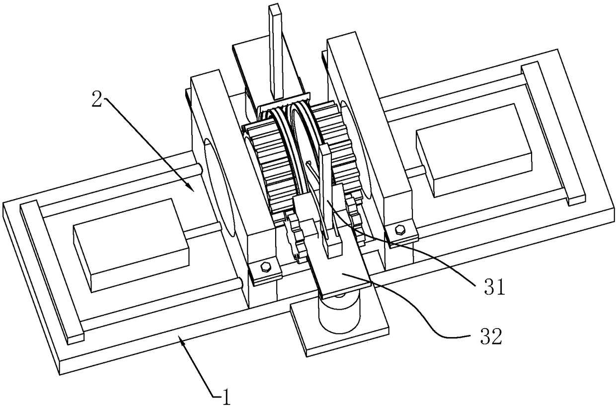
[0039] Embodiment 1: a kind of hot-melt butt joint equipment, such as Figure 1-2 , including a base 1, two pipe clamps 2 symmetrically installed on the base 1, and a driving member 21 for pushing the pipe clamps 2 to move.

[0040] The pipe clamp 2 is composed of a lower seat 22 and an upper seat 23. A semicircular hole is opened on each of the upper seat 23 and the lower seat 22. The bolt passes through the upper seat 23 and the lower seat 22 and connects a nut so that the upper seat 23 and the lower seat 22 are connected to form A circular hole through which a pipe passes. The driving part 21 is a cylinder, and the piston rod of the cylinder is connected with the lower seat 22. In order to make the pipe clamp 2 move smoothly, two guide posts 24 passing through the lower seat 22 are fixed on the base 1, and the lower seat 22 can move relative to the guide posts 24. .

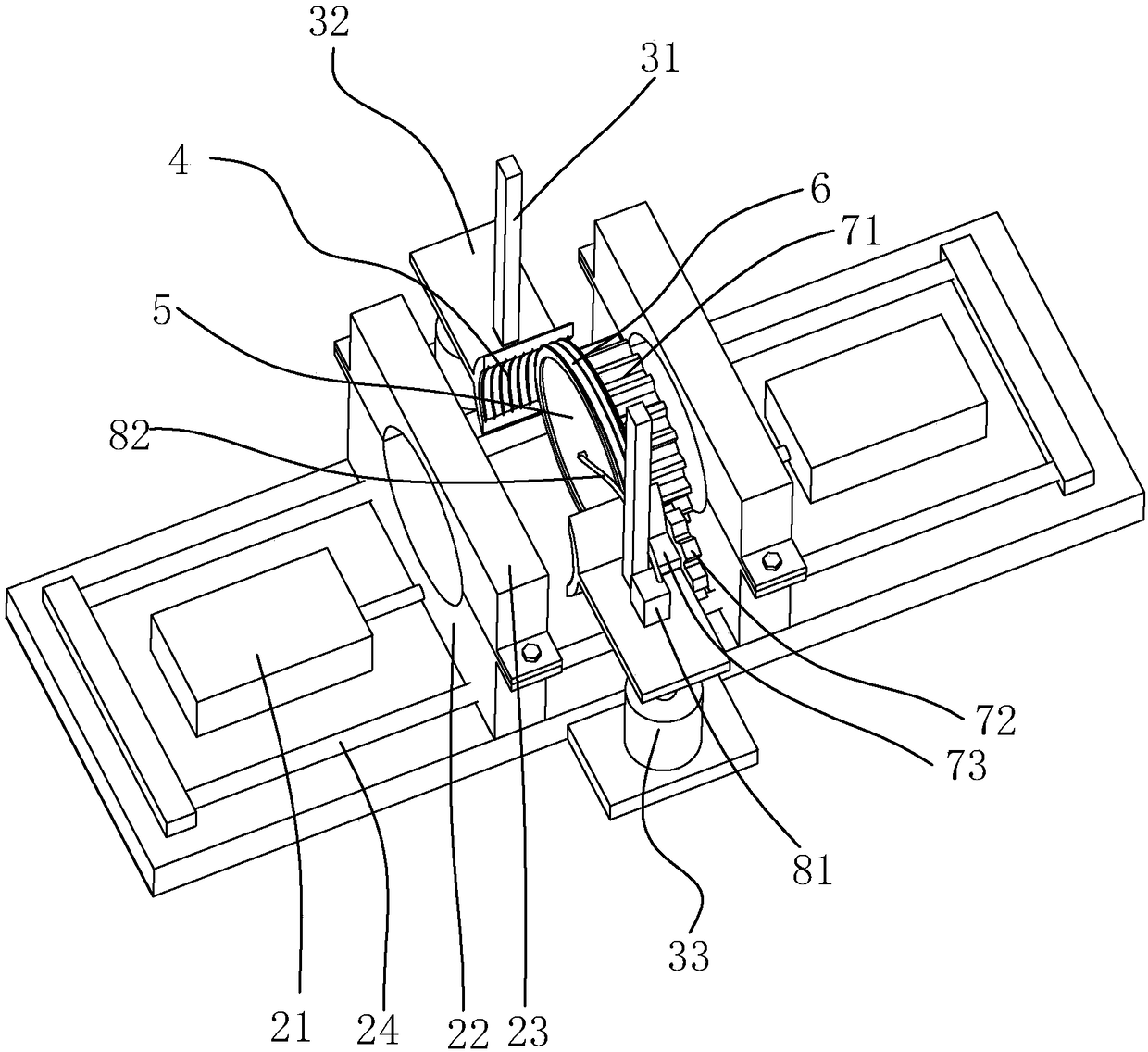
[0041] A guide rail 31 is fixed on the base 1, and the guide rail 31 is located in the middle of the two ...

Embodiment 2

[0043] Embodiment 2: A pipeline hot-melt butt joint process, comprising the following steps:

[0044] 1) Preparation: use a grinder to smooth and clean the end faces of the pipes to be connected, put the two pipes into the pipe fixture respectively and the pipes protrude out of the pipe fixture, and rotate the motor so that the two heating plates are in contact with the adjacent pipes respectively. The two heating plates are set at intervals.

[0045] 2) Heating: heating the heating plate to melt the part of the pipe contacting the heating plate; the heating temperature of the heating plate is 210±10°C.

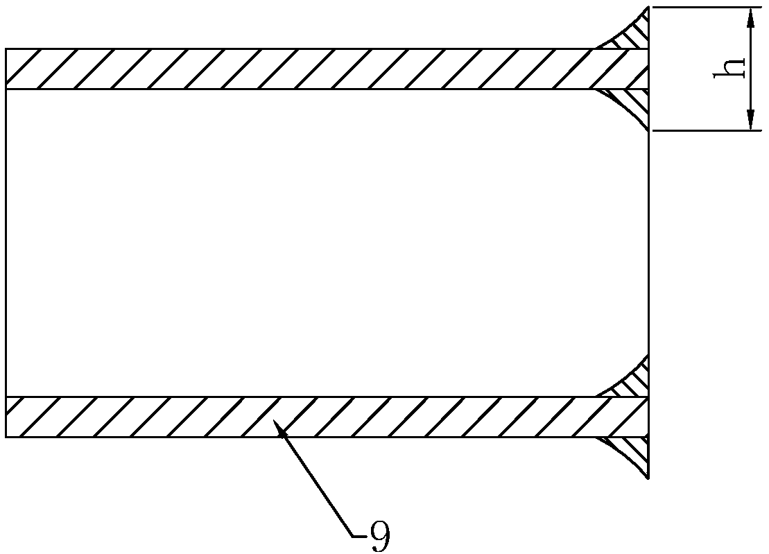
[0046] 3) Crimping: push the pipe to the heating plate so that the part of the pipe and the heating plate is deformed into a crimp; when the wall thickness of the pipe is 2-6.9mm, the height of the beading is 0.5mm; when the wall thickness of the pipe is 7-11.4mm , the curling height is 1mm; when the pipe wall thickness is 11.5-32.3mm, the middle curling height is 1.5mm.

...

Embodiment 3

[0050] Embodiment 3: A pipe hot-melt butt joint process, the difference from Embodiment 2 is that a polytetrafluoroethylene film is adhered to the end surface where the heating plate abuts with the pipe.


PUM

PropertyMeasurementUnit
diameteraaaaaaaaaa
lengthaaaaaaaaaa
thicknessaaaaaaaaaa

Abstract

The invention belongs to the field of pipeline welding, provides a pipeline hot melting butt joint technology and hot melting butt joint equipment and solves the problem that the correction is large when a pipeline is welded. According to the scheme, the pipeline hot melting butt joint technology comprises the following steps: 1, preparing: levelling and cleaning to-be-butt joint end faces of a pipeline, arranging two heating plates at an interval, and enabling the two heating plates to be propped against the adjacent pipeline; 2, heating: heating the heating plates to melt the part, propped against the heating plates, of the pipeline; 3, crimping: pushing the pipeline towards the heating plates to deform the part, propped against the heating plates, of the pipeline into curled edges; 4, switching: rotating the heating plates in the circumferential direction, moving the heating plates in the axial direction simultaneously to enable the heating plates to deviate from the pipeline propped against the heating plates, and removing the heating plates when the pipeline and the heating plates are separated from each other; and 5, carrying out pressure welding: pushing the melted part of the pipeline to be propped against the heating plates. As the heating plates rotate in the circumferential direction and can form shearing force during rotating, the pipeline and the heating plates canbe easily separated, and the axial or radial moving degree of the melted part of the pipeline is lowered to reduce correction.

Description

technical field [0001] The invention relates to the field of pipe butt joints, in particular to a pipeline hot-melt butt joint process and hot-melt butt joint equipment. Background technique [0002] With the development of the city, the underground sewage pipe network is becoming more and more perfect. When sewer pipes are corroded or worn over time they become defective and need to be replaced. [0003] At present, pipeline emergency repair technologies mainly include excavation and trenchless, and non-excavation techniques include trenchless traction, CIPP flip lining, ultraviolet light curing, and resin point repair. [0004] The traction pipe construction technology is a pipe renewal process that uses equipment to crush or split the original pipe from the inside, squeeze the original pipe fragments into the surrounding soil, form pipe holes at the same time, and simultaneously pull into the new pipe. It is mostly suitable for the repair and renewal of flexible pipes w...

Claims


Application Information

Patent Timeline
Patent Type & Authority Applications(China)
IPC IPC(8): B29C65/20B29L23/00
CPCB29C65/20B29L2023/00
Inventor 李文辉程鑫远刘东倚郑方斌项青东
Owner 杭州大江东城市设施管养有限公司
Why Eureka
Try Eureka