A heat collecting tube for dish solar reflector to gather heat

A solar reflector and heat collecting tube technology, which is applied to solar heat collectors, solar heat collectors using working fluids, and solar heat storage, etc. Due to the large initial investment and other problems, the effect of a wide range of heating medium, a simple structure and a short construction period can be achieved.

Active Publication Date: 2021-03-02
玉环未涞流体科技有限公司
View PDF10 Cites 0 Cited by
  • Summary
  • Abstract
  • Description
  • Claims
  • Application Information

AI Technical Summary

Problems solved by technology

[0007] 1. It is necessary to solve the problems of complex structure, large initial investment and long construction period of the existing solar thermal power generation system;
[0008] 2. To solve the problem of low heat collection efficiency of existing heat collection devices;
[0009] 3. It is necessary to solve the problems of high technical difficulty and high manufacturing cost of existing heat gathering devices

Method used


Image

  • A heat collecting tube for dish solar reflector to gather heat
  • A heat collecting tube for dish solar reflector to gather heat
  • A heat collecting tube for dish solar reflector to gather heat

Examples


Embodiment 1

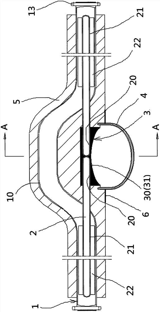
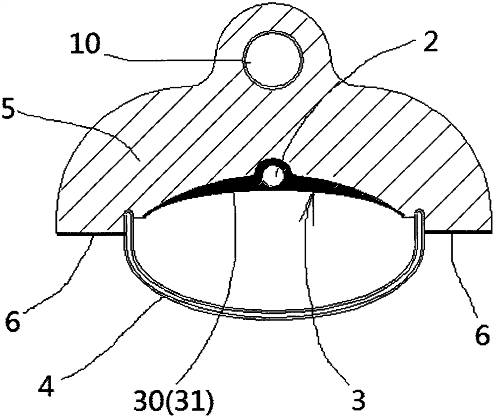
[0044] like figure 1 , figure 2 , image 3 and Figure 4 As shown in the figure, a heat collecting tube for dish solar reflectors includes a fluid pipe 1 , a heat pipe 2 and a light collecting head 3 .

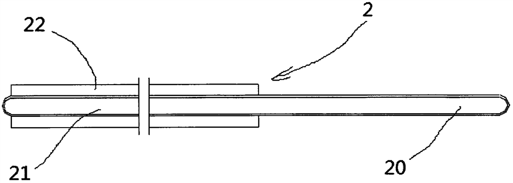
[0045] The lower side of the fluid pipeline 1 near the middle section is provided with the described focusing head 3, and the heat pipe 2 includes a heat absorbing section 20 (or claiming an evaporating section) and a heat dissipation section 21 (or claiming a condensing section), with the focusing head 3 being a boundary point, One heat pipe 2 is arranged on each of the left and right sides, and the heat absorbing sections 20 of two adjacent heat pipes 2 are wrapped inside by the focusing head 3 , and the heat dissipation section 21 is located in the fluid pipe 1 .

[0046] In practical application, the focusing head 3 is always on the focusing point of the dish-type parabolic reflector, and the focusing head 3 quickly transfers the accumulated heat to the heat transfer m...

Embodiment 2

[0055] like Figure 5 , Image 6 , Figure 7 and Figure 8 As shown in the figure, a heat collecting tube for dish solar reflectors includes a fluid pipe 1 , a heat pipe 2 and a light collecting head 3 .

[0056] The lower side of the fluid pipe 1 near the middle section is provided with a condenser head 3, and the heat pipe 2 includes a heat absorption section 20 (or an evaporation section) and a heat dissipation section 21 (or a condensation section). One heat pipe 2 is provided, and the heat-absorbing sections 20 of two adjacent heat pipes 2 are wrapped in it by the condensing head 3, and the heat-dissipating section 21 is integrated with the fluid pipe 1. In practical applications, the condensing head 3 is always in the At the converging point of the type parabolic reflector, the concentrating head 3 quickly transfers the accumulated heat to the heat transfer medium in the fluid pipe 1 through the heat dissipation section 21 of the heat pipe 2, so as to achieve the purp...

Embodiment 3

[0063] like Figure 9 As shown, an application in which no heat conduction fins are provided in the fluid pipeline 1 is presented, and the others are the same as those in Embodiment 2, and will not be repeated here.


PUM


Abstract

A heat collecting tube used for heat collection of a dish solar reflector, comprising a fluid pipe, a heat pipe, and a condensing head, characterized in that the underside of the fluid pipe near the middle section is provided with the condensing head, and the The heat pipe includes a heat absorption section (or an evaporation section) and a heat dissipation section (or a condensation section). With the light-condensing head as a boundary point, the left and right sides are respectively provided with the heat pipes, and the heat absorption sections of two adjacent heat pipes They are all wrapped in the condensing head, and the heat dissipation section is in the fluid pipe or integrated with the fluid pipe. In practical applications, the condensing head is always in the reflective At the focusing point of the mirror, the heat gathered by the focusing head is quickly transferred to the heat transfer working medium in the fluid pipeline through the heat dissipation section of the heat pipe, so as to achieve the purpose of high temperature heat collection.

Description

technical field [0001] The invention belongs to the technical field of solar heat utilization, and in particular relates to a technology of a heat collecting tube used for heat collection by a dish-type solar reflector. Background technique [0002] On the one hand, the level of human energy consumption continues to increase, on the other hand, conventional fossil energy is increasingly exhausted, and the pollutant emissions associated with conventional fossil energy are increasingly unable to meet people's demand for future energy. Solar energy, as an inexhaustible new clean energy, is getting more and more attention, and the development of solar energy is making progress day by day. Among them, solar power generation is an advanced development and application of solar energy. It converts solar energy into electrical energy through certain means to meet the electricity demand of modern society. [0003] Currently popular solar power generation is mainly divided into two fo...

Claims


Application Information

Patent Timeline
Patent Type & Authority Patents(China)
IPC IPC(8): F24S10/95F24S10/70F24S23/71F24S10/40F24S60/00
CPCY02E10/44
Inventor 李增清李渊
Owner 玉环未涞流体科技有限公司
Why Eureka
Try Eureka