
A method to obtain the maximum optical parametric generation conversion bandwidth at room temperature

An optical parameter and bandwidth technology, applied in optics, lasers, nonlinear optics, etc., can solve the problems of wavelength conversion bandwidth flatness that cannot be uniformly solved and improved, unevenness, etc., to achieve quasi-phase matching process, good The effect of flatness

Active Publication Date: 2021-07-02
NANJING UNIV OF POSTS & TELECOMM +1
View PDF0 Cites 0 Cited by
  • Summary
  • Abstract
  • Description
  • Claims
  • Application Information

AI Technical Summary

Problems solved by technology

However, the main problem in the above methods is that the expansion of the wavelength conversion bandwidth and the flatness of the bandwidth still cannot be solved and improved uniformly, that is, while the bandwidth is getting larger, the top, especially the degeneration point corresponding to the pump light ( twice the wavelength of the pump light) will become uneven

Method used


Image

  • A method to obtain the maximum optical parametric generation conversion bandwidth at room temperature
  • A method to obtain the maximum optical parametric generation conversion bandwidth at room temperature
  • A method to obtain the maximum optical parametric generation conversion bandwidth at room temperature

Examples


Embodiment Construction

[0014] Objects, advantages and features of the present invention will be illustrated and explained by the following non-limiting description of preferred embodiments. These embodiments are only typical examples of applying the technical solutions of the present invention, and all technical solutions formed by adopting equivalent replacements or equivalent transformations fall within the protection scope of the present invention.

[0015] Starting from the group velocity matching technology and the quasi-phase matching technology, the present invention designs a method for realizing wider and flatter optical parameter generation conversion bandwidth by using non-periodically polarized crystals. In the following, the non-periodic poled lithium niobate crystal is taken as the optimal embodiment for description.

[0016] The invention discloses a method for obtaining the maximum optical parameter generation conversion bandwidth at room temperature. The material used in the method ...


PUM

PropertyMeasurementUnit
lengthaaaaaaaaaa

Abstract

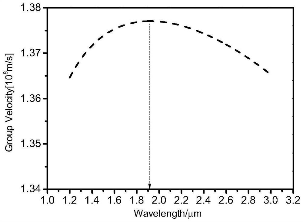
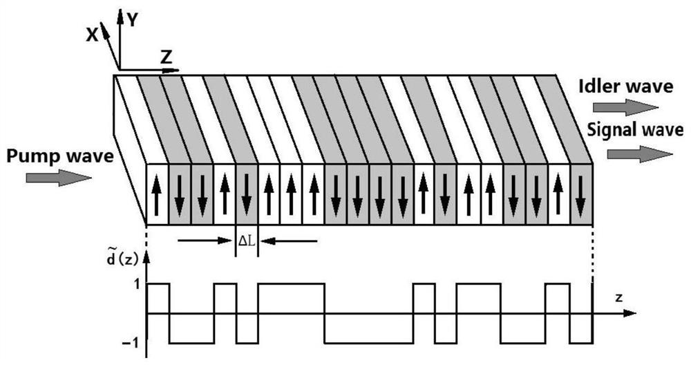
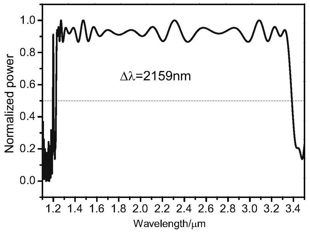
The invention discloses a method for obtaining the maximum optical parameter generation conversion bandwidth at room temperature. In the method, the material used for the crystal is lithium niobate crystal, which has a non-periodic structure. At 24 degrees Celsius, the pump light of 0.9 microns is selected Wavelength, through the designed aperiodic structure to make up for the phase mismatch between the wavelength degradation point of the pump light and the matching point of the wavelength group velocity of the signal light and idler light, so that the phase mismatch between the three can meet the optical parameter When the phase matching condition is generated, the maximum optical parameter generation bandwidth of 2159 nanometers can be obtained. The crystal shape is a cuboid structure. When used, the incident direction of the beam is perpendicular to the polarization direction, and along the incident direction of the beam, it is polarized into unit domains of equal length. The polarization direction of each unit domain can be selected upward or downward. The crystal can realize larger and flatter optical parameter generation conversion bandwidth between the group velocity matching points of signal light and idler light under the condition of quasi-phase matching.

Description

technical field [0001] The invention relates to a method for obtaining the conversion bandwidth of maximum optical parameter generation at room temperature. Background technique [0002] Optical parameter generation has a wide range of applications in the fields of laser spectroscopy and trace gas detection in the mid-infrared spectral region [1, Masashi Abe, Yoshiki Nishida, Osamu Tadanaga, Akio Tokura, Hirokazu Takenouchi, Optics Letter, 2016 41 1380-1383], [2. M. Vainio, L. Halonen, Physical Chemistry Chemical Physics, 2012 00 1-3]. However, when quasi-phase-matching technology is used to generate optical parametric lasers, only a narrow bandwidth can be obtained because of the efficiency conversion problem. In response to this problem, many solutions have been proposed at home and abroad, such as non-collinear beam devices [Bortz M L, Fujimura M, Fejer M M.Increased acceptance bandwidth for quasi-phasematched second harmonic generation in LiNbO3waveguides[J]. E1electron...

Claims


Application Information

Patent Timeline
Patent Type & Authority Patents(China)
IPC IPC(8): G02F1/355G02F1/39H01S3/108
CPCG02F1/355G02F1/39H01S3/108
Inventor 蒋建王凯张建东张祖兴
Owner NANJING UNIV OF POSTS & TELECOMM
Learn More