Patrol control system for offshore boosting station
An offshore booster station, central controller technology, applied in general control systems, control/regulation systems, program control, etc., can solve problems such as low efficiency of booster station inspections, reduce the number of inspections going out to sea, and reduce transportation costs. The effect of reducing maintenance costs and improving inspection efficiency
Inactive Publication Date: 2018-08-07
CHINA ENERGY ENG GRP GUANGDONG ELECTRIC POWER DESIGN INST CO LTD
7 Cites 6 Cited by
AI-Extracted Technical Summary
Problems solved by technology
[0004] Based on the above analysis, it is necessary to provide an offshore booster station inspection and...
View moreMethod used
Above-mentioned state analysis can be, for example: second server 144 according to the received state information and environmental information, counts the running current, voltage, switch state, ambient temperature change, Humidity changes, smoke conditions and SF6 gas concentration and other information. Generate the latest status monitoring report or update historical monitoring report based on the latest status information and environmental information obtained, which is convenient for operation and maintenance personnel to view and track management in real time, or export the latest status monitoring report for reporting. The aforementioned records and/or reports may be stored in the form of reports.
In one of the embodiments, the central controller 122 of the inspection terminal 12 can send a trigger signal to the security device 16 when starting, so that the security device 16 controls the current checked compartment of the offshore step-up station according to the trigger signal. The lights work synchronously. That is to say, when the inspection terminal 12 starts the inspection work, it can synchronously control the lighting of the currently inspected cabin through the security device 16, so as to improve the accuracy of the video recognition inspection under low brightness conditions. In this way, through the light linkage during the inspection, the accuracy of the status information obtained during the inspection in each time period can be effectively ensured, and the inspection work can be performed around the clock by using the inspection terminal 12, and the inspection efficiency is higher.
In this way, the monitoring platform 14 can realize the timely acquisition and transmission of state information and environmental information through the setting of the first server 142 and the second server 144, and at the same time, effectively carry out state and environmental monitoring to each cabin and its target equipment 40 And send the scheduling plan to the inspection terminal 12, and the joint security device 16 will control and process the faults in time to improve the efficiency of inspection and fault handling.
In this way, through the design and cooperative operation of the inspection terminal 12, the inspection platform 14 and the security device 16, the automatic inspection of each cabin of the offshore booster station can be realized, effectively and timely responding in each cabin of the offshore booster station The abnormal operating status and abnormal environmental status of each target equipment improves the intelligence of the operation and maintenance management of the offshore booster station, thereby greatly improving the inspection efficiency. Through the intelligent linkage of the security device 16, it is possible to effectively avoid the deterioration of general equipment failures, resulting in the damage of the target equipment and the need to arrange operation and maintenance personnel to come to the site for maintenance, thereby reducing equipment losses and greatly reducing the operation and maintenance costs of offshore booster stations . The environmental control of the power distribution room responds quickly, which can better meet the requirements of automatic operation and maintenance of the power grid.
Like this, through the above-mentioned analysis process of second server 144, can facilitate land monitoring system to carry out real-time monitoring and early warning to each cabin of offshore step-up station each target equipment 40 operating condition, to each compartment of sea step-up station The abnormal conditions of the indoor environment are monitored and tracked, and there is no need to send operation and maintenance personnel to the scene to deal with them under normal abnormal conditions, and the abnormal conditions on site can be known in advance, which greatly improves the comprehensive inspection efficiency of offshore booster stations and reduces operation and maintenance costs. .
Specifically, after the security control module 162 receives the fault control instruction that the first server 142 sends, the fault information of the fault can be determined according to the fault control command, for example, the cabin where the fault is determined, the type of fault (such as overtemperature , overhumidity or SF6 gas concentration is too high, etc.) and the fault level, generate a control command according to the fault information, and send the control command to the security device 164 of the corresponding cabin. After receiving the control instruction, the corresponding security device 164 enters the working state to process the fault. In this way, through the cooperation of the security control module 162 and the security device 164, the abnormal environment can be dealt with early and effectively, avoiding the damage caused by the reversible abnormality of the target device 40 deteriorating into an irreversible fault, and also avoiding the impact of the environmental abnormality on the normal device. Adverse effects, reduce equipment failure rate, improve inspection efficiency and ultimately reduce the operation and maintenance cost of the booster station.
Specifically, the inspection terminal 12 can communicate with the inspection platform 14 through the central controller 122, and gathers the status information of the target equipment in the inspection process by the state monitoring module 124; During the process, the environmental information of each cabin is collected synchronously or asynchronously. The state monitoring module 124 and the environment monitoring module 126 respectively send the collected state information and environment information to the patrol platform 14 through the central controller 122 . The status monitoring module 124 and the environment monitoring module 126 respectively receive the scheduling instructions sent by the patrol platform 14 through the central controller 122 . In this way, the inspection terminal 12 can effectively complete the collection of the required state information and environmental information through the central controller 122, the state monitoring module 124 and the environmental monitoring module 126, and realize communication with the inspection platform 14, and the information collection efficiency is improved. higher.
Thus, by identifying the collocation design of the camera 1241 and the partial discharge sensor 1242, covering all kinds of equipment state information required to be collected by various target equipment 40 in each cabin of the booster station at sea, the state information obtained is more comprehensive and collected efficient.
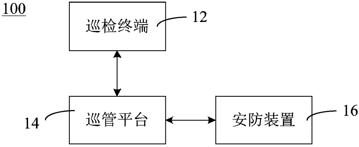
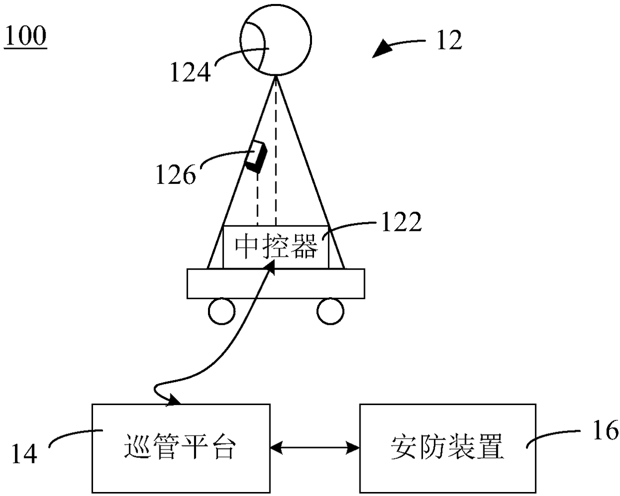
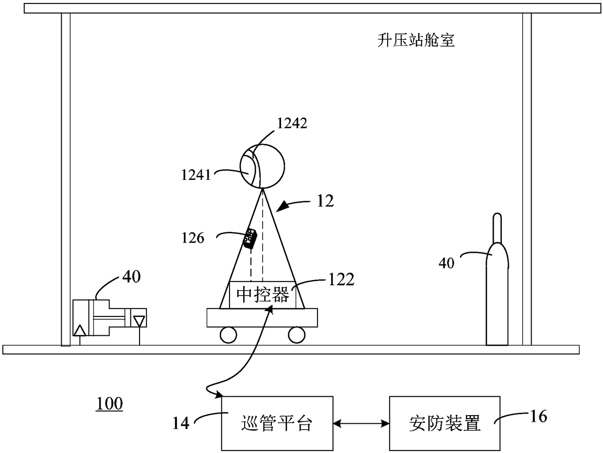
[0032] Offshore wind farms are widely distributed and the offshore climate environment is relatively harsh, and the incidence of faults is higher than that of land farms, which often leads to difficulty in carrying out inspections of offshore wind farms, and the cost is relatively high. The offshore booster station in the offshore wind farm i...
View moreAbstract
The invention discloses a patrol control system for an offshore boosting station. The patrol control system comprises a routing inspection terminal for carrying out routing inspection on all cabins tocollect equipment state information and indoor environment information, a patrol management platform for carrying out analyzing and scheduling according to the state information and sending out a fault control command according based on the environmental information, and a security and protection device for carrying out fault control processing based on the fault control command. The patrol management platform is in communication connection with the routing inspection terminal and the security and protection device. The routing inspection terminal carries out routing inspection on all cabinsof an offshore boosting station; with linked control of the patrol management platform and the security and protection device, control processing is carried out on a fault timely and warning is sent out; the abnormal situation of the offshore boosting station is controlled timely; and the number of times of routing inspection on the sea by the operation and maintenance staff is reduced or the operation and maintenance time is saved for the operation and maintenance staff and a safety sea condition option is provided for the operation and maintenance staff. Therefore, the routing inspection efficiency of the offshore wind plant is improved substantially; the operation and maintenance costs are lowered; and the intelligent operation of the offshore boosting station is realized.
Application Domain
Technology Topic
Image
Examples
- Experimental program(1)
Example Embodiment
[0031] The specific implementation of the marine booster station patrol control system of the present invention will be described in detail below with reference to the accompanying drawings. The preferred embodiment of the invention is shown in the drawings. However, the present invention can be implemented in many different forms and is not limited to the embodiments described herein. On the contrary, the purpose of providing these embodiments is to make the disclosure of the present invention more thorough and comprehensive.
[0032] Offshore wind farms are distributed in a wide area and the offshore climate environment is relatively harsh, and the failure rate is higher than that of onshore power plants. This often makes it difficult to carry out the inspection work of offshore wind farms and the cost is high. The sea booster station in the offshore wind farm is responsible for the transmission and distribution of the electric energy produced by the entire farm, and is an important part of the operation and management of the offshore wind farm. In order to ensure the safe, stable and economical operation of the sea booster station and ensure the economic benefits of the offshore wind farm, it is necessary to build a fully functional, stable and reliable sea booster station’s comprehensive inspection system for all cabins, and the power distribution of the offshore wind farm Centralized and intelligent management of the chambers realizes the intelligent operation of each cabin of the sea booster station.
[0033] See figure 1 , The embodiment of the present invention provides a patrol and control system 100 for an ocean booster station, which includes a patrol terminal 12, a patrol platform 14 and a security device 16. The patrol platform 14 communicates with the patrol terminal 12 and the security device 16 respectively. The patrol terminal 12 is used to patrol each cabin of the sea booster station, collect the status information of the target equipment in each cabin and the environmental information of each cabin, and send it to the patrol platform 14. After acquiring the status information and environmental information, the patrol management platform 14 performs status analysis on the status information, schedules the patrol terminal 12 according to the analysis results, and generates a fault control instruction and sends it to the security device 16 when a fault is detected according to the environmental information. After receiving the fault control instruction, the security device 16 controls and processes the fault according to the fault control instruction.
[0034] Among them, each cabin can be, but not limited to, the centralized control room, primary equipment room, secondary equipment room, fire fighting equipment room, ventilation room, main transformer room, gas insulated combined electrical equipment (GIS: Gas Insulated Switchgear) room, Diesel engine room and power distribution room. The target equipment can be various power equipment in each cabin of the booster station, such as high-voltage cabinets, transformers, switches in the sea booster station, circuit breakers, current transformers (CT), voltage transformers (PT), lightning arresters, porcelain insulators And other electrical screen cabinet equipment. The status information can be the operating status, switch status and/or appearance status of the target equipment in each cabin of the sea booster station, such as the reading of the power meter of the target equipment, the status of the indicator light, the status of alarm indication, and the opening and closing of the knife Status, partial discharge status, equipment operating noise, or other information that can characterize equipment operating status. The environmental information can be the indoor environment information of each cabin of the sea ascending pressure station, for example, it can be the indoor temperature, humidity, noise, and SF of the cabins of the sea ascending pressure station. 6 (Sulfur hexafluoride) and other chemical gases, smoke or other information that can characterize the indoor environment.
[0035] Faults can be caused by various abnormal operating conditions of the target equipment or abnormal conditions caused by the indoor environment being affected by the outdoor environment, such as but not limited to abnormal partial discharge of the high-voltage cabinet, excessive temperature, excessive equipment operation noise, and equipment Overcurrent of a certain component causes smoke, excessive indoor humidity, indoor SF 6 Concentration is too high and indoor flooding occurs. The aforementioned faults can generally correspond to, but are not limited to, fault information of various fault locations, fault types, and/or fault levels.
[0036] It can be understood that the communication connection between the patrol terminal 12, the patrol platform 14 and the security device 16 can be a wired connection of a data transmission line such as a submarine optical cable, or a wireless communication connection, as long as the communication between the components can be realized. The function is all right, and this manual is not limited. The inspection terminal 12 may be one or more integrated inspection equipment deployed on the sea booster station. The patrol management platform 14 may be a patrol management platform composed of servers with functions such as data management, analysis, monitoring and scheduling. The security device 16 may be a centralized control device that provides security protection for the sea booster station.
[0037] Specifically, the patrol terminal 12 can perform patrol inspections on the target equipment in each cabin of the sea booster station in the manner of automatic patrol inspections during the set working hours, patrol inspections scheduled by the patrol management platform 14, or manual patrol inspections. For example, video recognition patrol and/or sensor detection patrol, collect the status information of each target device in each cabin and the environmental information of each cabin. The patrol management platform 14 can obtain collected status information and environmental information from the patrol terminal 12 in real time, and can also send control instructions to the security device 16 or obtain feedback information of the failure processing result from the security device 16. The patrol management platform 14 can perform a status analysis on the obtained status information, and obtain a status analysis result of each target device based on the status information, so as to schedule the patrol terminal 12 according to the status analysis result of each target device. When the patrol management platform 14 detects a fault based on environmental information, it can generate a corresponding fault control command and send it to the security device 16. The fault control command can contain corresponding fault information, such as fault type, fault location, and/or fault level. . After receiving the fault control instruction, the security device 16 can perform corresponding processing on the fault according to the fault information corresponding to the fault control instruction.
[0038] In this way, through the design and coordinated operation of the inspection terminal 12, the inspection platform 14 and the security device 16, the automatic inspection of the cabins of the sea ascending station can be realized, and the targets in the cabins of the sea ascending station can be effectively and timely responded to. The abnormal operation state and abnormal environmental state of the equipment have improved the intelligence of the operation and maintenance management of the sea booster station, thereby greatly improving the inspection efficiency. Through the intelligent linkage of the security device 16, it can effectively avoid the deterioration of general equipment failures, which leads to the damage of the target equipment and the need to arrange operation and maintenance personnel to be on site for maintenance. This can also reduce equipment losses and greatly reduce the operation and maintenance costs of the ocean booster station . The environmental control response of the power distribution room is fast, which can better meet the requirements of power grid automation operation and maintenance.
[0039] See figure 2 with image 3 , The solid double arrow connecting line in the two figures indicates the communication connection, and the dashed line indicates the electrical connection. In one of the embodiments, the inspection terminal 12 includes a central controller 122, a state monitoring module 124, and an environmental monitoring module 126. The central controller 122 is electrically connected to the state monitoring module 124 and the environment monitoring module 126 respectively. The central controller 122 is in communication connection with the patrol platform 14. The central controller 122 controls the status monitoring module 124 to collect the status information of the target equipment in each cabin, and controls the environment monitoring module 126 to collect the environment information, and sends the status information and environment information to Patrol platform 14.
[0040] It can be understood that the inspection terminal 12 may be a wheeled or guide rail type inspection robot or a customized inspection robot commonly used in the market. The setting central controller 122 can be the control MCU of the inspection robot and its main board circuit module, or it can be an auxiliary MCU directly controlled by the control MCU of the inspection robot, used for the main control status monitoring module 124 and the environment monitoring module 126. The state monitoring module 124 may be a module integrated with a video recognition device and a partial discharge detection instrument, and can be used for video inspection and partial discharge detection (partial discharge detection) of the target device. The environmental monitoring module 126 may be a module integrated with various environmental monitoring sensors, and may be used to detect indoor environmental information of each cabin. The scheduled working time can be the automatic inspection cycle time set by the operation and maintenance personnel when the inspection terminal 12 is deployed, or the inspection time when the inspection platform 14 is scheduled, or it can be manually controlled by the operation and maintenance personnel. The specific time of the inspection.
[0041] Specifically, the inspection terminal 12 can communicate with the inspection platform 14 through the central controller 122, and collect the status information of the target device during the inspection process through the status monitoring module 124; and synchronize during the inspection process through the environmental monitoring module 126 Or asynchronously collect environmental information of each cabin. The state monitoring module 124 and the environmental monitoring module 126 respectively send the collected state information and environmental information to the patrol management platform 14 through the central controller 122. The state monitoring module 124 and the environmental monitoring module 126 receive the scheduling instructions sent by the patrol management platform 14 through the central controller 122 respectively. In this way, the patrol terminal 12 can effectively complete the collection of required status information and environmental information through the central controller 122, the status monitoring module 124, and the environmental monitoring module 126, and communicate with the patrol platform 14, and the information collection efficiency Higher.
[0042] In one of the embodiments, the communication connection between the central controller 122 and the patrol management platform 14 is wireless communication. In this way, through wireless communication, the inspection range of the inspection terminal 12 can be made larger, which facilitates the overall inspection of the booster station.
[0043] In one of the embodiments, the status monitoring module 124 includes a recognition camera 1241 and a partial discharge sensor 1242. The recognition camera 1241 is used to perform a video recognition inspection on the target device 40, and the partial discharge sensor 1242 is used to perform a partial discharge detection on the target device 40, and collect status information of the target device 40.
[0044] In other words, the status monitoring module 124 can perform video recognition inspections on the target device 40 by configuring the recognition camera 1241, and collect most of the required status information such as meter readings, device model, appearance status, switch status, etc. Such as image 3 Application example shown. The recognition camera 1241 may be various existing cameras with video tracking and recognition functions. The partial discharge sensor 1242 is used to collect information about the partial discharge state of the high-voltage target device 40. All the collected status information is summarized by the central controller 122 and sent to the patrol platform 14. It can be understood that the partial discharge sensor 1242 may be various commonly used partial discharge detectors.
[0045] In this way, through the matching design of the recognition camera 1241 and the partial discharge sensor 1242, various types of equipment status information required to be collected by various target equipment 40 in each cabin of the sea booster station are covered, and the obtained status information is more comprehensive and the collection efficiency is high.
[0046] In one of the embodiments, such as image 3 Application example shown. The environmental monitoring module 126 includes a temperature sensor, a humidity sensor, a smoke sensor, and a chemical gas sensor. It can be understood that the central controller 122 can be electrically connected to a temperature sensor (or an infrared camera using infrared temperature measurement), a humidity sensor, a noise sensor, a smoke sensor, and a chemical gas sensor to control the temperature sensor, humidity sensor, smoke sensor, and The chemical gas sensor patrols and detects the indoor environment of each cabin of the sea ascending pressure station, collects environmental information and sends it to the patrol platform 14 through the central controller 122.
[0047] In other words, the environmental monitoring module 126 may be provided with a temperature sensor for indoor temperature monitoring, a humidity sensor for indoor humidity monitoring, a noise sensor for indoor equipment noise monitoring, a chemical gas sensor for indoor chemical gas concentration monitoring, and an indoor Smoke sensor for smoke monitoring. Among them, the temperature sensor can also be replaced by an infrared camera; the chemical gas can be, for example, SF 6 Gas or other types of chemical gases that need to be monitored. The aforementioned environmental information may be temperature information, humidity information, smoke information, and chemical gas concentration information of each cabin.
[0048] Specifically, the inspection terminal 12 can perform mobile inspections by setting the above-mentioned recognition camera 1241 and various sensors, so as to monitor the operating status of the target device 40 while monitoring indoor environmental information. In this way, through the environmental monitoring module 126 provided with various sensors, the operating state of the target device 40 and the environmental monitoring in each cabin can be realized, and the information monitoring cost is low and the efficiency is high.
[0049] In one of the embodiments, the central controller 122 of the inspection terminal 12 can send a trigger signal to the security device 16 when it is started, so that the security device 16 can control the lighting of the currently inspected compartment of the sea booster station according to the trigger signal. jobs. In other words, when the inspection terminal 12 starts the inspection work, the security device 16 can synchronously control the turn-on lights of the currently inspected cabin, so as to improve the accuracy of the video recognition inspection in the low brightness situation. In this way, the light linkage during the inspection can effectively ensure the accuracy of the status information obtained from the inspection in each time period. The inspection terminal 12 can be used to perform the inspection work around the clock, and the inspection efficiency is higher.
[0050] In one of the embodiments, the inspection terminal 12 can also be associated with the video surveillance system installed in each cabin of the booster station, and the surveillance cameras in each cabin can use the video surveillance system to alert the general equipment or areas in the general area before warning (for example, At least 30 seconds) and after alarm (for example, at least 30 seconds), alarm video storage and identification, for example, when an illegal intruder or animal is monitored, an alarm is automatically triggered, and the alarm video is stored on the patrol platform 14 and identified. Cameras that monitor important areas can be set to perform 24-hour automatic recording and storage for a long period of time (for example, one month). The importance level of each surveillance camera can be preset by operation and maintenance personnel.
[0051] Among them, the above-mentioned video recording can be stored on the patrol management platform 14 in the form of a video stream in units of seconds. The time interval of each video file stored on the patrol platform 14 may not exceed 5 minutes, and the size of the video file may not exceed 100MB. The specific setting value can be set according to the data storage capacity of the patrol platform 14 or data storage needs The aforementioned numerical values are only examples and not specific limitations to the embodiments of the present invention. In this way, the efficiency of inspection can be further improved by cooperating with the installed video surveillance system.
[0052] See Figure 4 In the figure, except for the electrical connection of the dashed line meter inside the patrol terminal 12, the remaining double-arrow dashed lines indicate communication connections. In one of the embodiments, the patrol platform 14 includes a first server 142 and a second server 144 that are communicatively connected. The first server 142 is communicatively connected to the inspection terminal 12 and the security device 16 respectively. The second server 144 is communicatively connected to the inspection terminal 12. The first server 142 obtains the status information and environmental information, and sends the status information to the second server 144, and performs environmental monitoring according to the environmental information. When a failure is detected, a failure control instruction is generated and sent to the security device 16. The second server 144 is configured to receive status information, perform status analysis according to the status information, generate status monitoring reports and/or abnormal alarms of the target device 40 according to the analysis results, and generate a scheduling plan; wherein the scheduling plan is used to instruct the inspection terminal 12 Perform inspections.
[0053] It can be understood that the patrol management platform 14 can be composed of a second server 144 installed in the land management center and a first server 142 in the secondary equipment room of the sea booster station. The installation location is only an example, and the specific location can also be Other cabins. Both the first server 142 and the second server 144 may be information collection and processing devices constituted by data servers. The environmental information may be stored on the first server 142 for a preset period of time, for example, a period of one month. The specific duration can be set according to operation and maintenance needs. For example, when the second server 144 needs to perform environmental tracking and analysis, the data volume and range setting of environmental information need to be called to ensure the accuracy of environmental data analysis.
[0054] Specifically, the first server 142 may obtain the collected state information and environmental information from the state monitoring module 124 and the environmental monitoring module 126 through the central controller 122 of the inspection terminal 12, and then send the state information to the second server 144. The first server 142 performs environmental monitoring according to the obtained environmental information. When a fault is detected, such as indoor SF 6 If the gas content is too high, the corresponding SF will be generated 6 The leaked fault control instruction is sent to the security device 16, so that the security device 16 performs control processing according to the fault control instruction. For example, the fan can be turned on for indoor exhaust treatment to eliminate excessive indoor SF 6 gas. For another example, when it is detected that the indoor humidity is greater than the set humidity threshold, the first server 142 may send a humidity fault control instruction to the security device 16, so that the security device 16 controls the corresponding air conditioner or fan to turn on, and adjusts the indoor humidity to the humidity threshold. Within.
[0055] After receiving the status information, the second server 144 analyzes the status of each target device 40 according to the status information, generates a status monitoring report and/or abnormal alarm of each target device 40 according to the analysis result, and generates a scheduling plan. The scheduling plan may be sent to the inspection terminal 12 to instruct the inspection terminal 12 to perform the corresponding automatic inspection, or the operation and maintenance personnel may remotely manually control the controlled inspection. For example, when the second server 144 detects an abnormal partial discharge in one of the high-voltage cabinets in the analysis result, the patrol inspection terminal 12 is dispatched to perform a second patrol on the high-voltage cabinet. The status monitoring report can be used to display the current operating status of each target device 40, and it is convenient for operation and maintenance personnel to formulate a temporary inspection scheduling plan based on the status monitoring report. The second server 144 can also analyze and monitor abnormal conditions in the status information. For example, when the meter readings of one or more of the target devices 40 are abnormal, it outputs an abnormal alarm to remind the operation and maintenance personnel to perform abnormal investigations, or perform temporary inspections on the inspection terminal 12 The scheduling of inspections to confirm abnormal conditions.
[0056] In this way, the patrol management platform 14 can realize the timely acquisition and transmission of status information and environmental information through the settings of the first server 142 and the second server 144, and at the same time, effectively perform status, environmental monitoring and patrolling of each cabin and its target equipment 40. The inspection terminal 12 issues a scheduling plan, and the security device 16 performs timely control and processing of faults that occur, thereby improving the efficiency of inspection and fault handling.
[0057] In one of the embodiments, the first server 142 may also actively send the environmental information and the processing result returned by the security device 16 after processing the fault to the second server 144, or for the second server 144 to call to make the second server 144 The server 144 can perform environmental monitoring and recording according to the environmental information and the processing result of the fault processing. For example, recording the indoor temperature, humidity and SF of each cabin of the sea ascending station 6 The gas content and fault handling conditions are provided for real-time reference and tracking management by operation and maintenance personnel to improve the inspection efficiency of the sea booster station.
[0058] In one of the embodiments, the above-mentioned status information may be information such as videos and pictures, or may be information such as meter readings, switch status, light and dark or color of indicators recognized from the video or pictures. The environmental information may be numerical information in the form of a chart. In this way, through the above-mentioned form of status information and environmental information, the patrol platform 14 can facilitate data processing to more intuitively reflect the changes in the operating status of each target device 40 and its trend of change, so as to realize the target device 40 and the indoor environment. Visual and predictable supervision.
[0059] In one of the embodiments, the first server 142 may be an information master control server. The second server 144 may be an analysis scheduling server. The communication connection between the information master control server and the analysis dispatch server includes a wireless communication connection and/or an optical cable connection.
[0060] It can be understood that one or more information master control servers can be configured in each booster station to master the inspection terminal 12 and security device 16 of the booster station to complete the acquisition and previous transmission of status information and environmental information, and The security device 16 is mobilized to control and process various types of failures that occur. The analysis and dispatch server can include one or more. The analysis and dispatch server can communicate and connect to the information master control server through any one or a combination of bus, submarine optical cable and wireless, so as to realize the above-mentioned information acquisition, analysis and processing and inspection. Check scheduling. The specific number of information master control servers and analysis scheduling servers can be determined according to the amount of information actually collected and the requirements for information processing speed.
[0061] Specifically, the information master control server may store the set environmental information types and threshold information of various types of environmental information. Types of environmental information can be temperature, humidity, smoke, and SF, for example 6 Gas, etc., the threshold information of environmental information can be, for example, a temperature threshold (such as 0°C≤T≤50°C), a humidity threshold, a smoke concentration threshold, and SF 6 Gas concentration threshold, etc. The information master control server can perform environmental monitoring on the acquired environmental information, and after detecting a fault, it can send a fault control instruction corresponding to the fault to the security device 16. In this way, by constructing the first server 142 and the second server 144 through specific servers, the data analysis and processing efficiency is high, and the intelligent inspection of the booster station is realized.
[0062] For example, when the high-voltage cabinet is operated for a long time under high load or the indoor temperature is higher than the threshold value of the ambient temperature allowed by the normal operation of various equipment due to the high temperature and sunshine outside, the information master control server sends a high temperature fault control instruction to the security device 16; the security device 16 can Determine the source location of the temperature abnormality according to the high temperature fault control command or according to the magnitude of the temperature exceeding the threshold value of the ambient temperature, control the opening and the duration of the air conditioner, and adjust the indoor temperature to within the threshold value of the ambient temperature. For another example, when sea level rise causes the water level to be too close to the floor of some cabins of the sea pressure station or sea fog invades, causing the indoor humidity to exceed the allowable indoor humidity threshold, the information master control server detects the abnormal humidity fault from the humidity information and then Send an over-humidity fault control instruction to the security device 16; the security device 16 can determine the size of the humidity exceeding the ambient humidity threshold according to the over-humidity fault control instruction, control the time for the air conditioner and/or fan to turn on and on, and adjust the indoor humidity to the environment Within the humidity threshold, eliminate the normal operation of the equipment in the power distribution room by the environmental humidity in time.
[0063] The above-mentioned status analysis may be, for example, the second server 144, according to the received status information and environmental information, counts the operating current, voltage, switch status, environmental temperature change, humidity change, Smoke condition and SF 6 Information such as gas concentration. Generate the latest status monitoring report or update the historical monitoring report based on the obtained latest status information and environmental information, which is convenient for operation and maintenance personnel to view and track management in real time, or export the latest status monitoring report for reporting. The aforementioned records and/or reports can be stored in the form of reports.
[0064] The second server 144 can also perform an abnormality analysis based on the fault information contained in the status information and the environmental information, to identify and locate the target device 40 that has failed and the type of environmental abnormality, and prompt and alert the unhandled failures so that the operation and maintenance personnel can timely Carry out targeted processing; the processed faults can be archived and stored, so that the operation and maintenance personnel can call the corresponding fault alarms and processing information when needed.
[0065] In one of the embodiments, the second server 144 may adopt a cluster configuration. In other words, the second server 144 may be a distributed server network composed of multiple analysis scheduling servers. In this way, the performance of the data management analysis of the second server 144 can be greatly improved.
[0066] In one of the embodiments, the second server 144 can perform a fault analysis on the acquired status information, the environmental information and the fault processing result collected from the first server 142, and obtain the result of the fault analysis, and perform the fault analysis based on the result of the fault analysis. Fault prediction: Send the results of fault analysis and predictions to the onshore monitoring system of the wind farm to provide early warning of abnormal conditions, facilitate operation and maintenance personnel to make operation and maintenance decisions and respond to potential abnormal conditions in advance. Among them, failure analysis can be based on specific operation and maintenance needs, using common failure analysis methods to analyze based on status information, environmental information, and failure processing results, which are not limited in this manual.
[0067] In this way, through the above-mentioned analysis and processing of the second server 144, it is convenient for the onshore monitoring system to perform real-time monitoring and early warning of the operation status of each target device 40 in each compartment of the sea ascending station, and to monitor the indoor environment of each compartment of the sea ascending station. Monitoring and tracking records of abnormal conditions, no need to send operation and maintenance personnel to the site for handling under general abnormal conditions, and the abnormal conditions on the site can be known in advance, which greatly improves the overall inspection efficiency of the sea booster station and reduces operation and maintenance costs.
[0068] For example, the second server 144 can analyze the operating status of different target devices 40 in different time periods and the trend of changes in their status based on the status information, environmental information, and failure processing results, so as to identify or facilitate the operation and maintenance personnel to discover potential problems of the target device 40 in time. , And can analyze potential problems and generate suggestions for solutions. The second server 144 may also synthesize the historical status information and environmental information of the patrol inspection and the fault processing result, so that the cause of the common fault can be determined when the common fault is detected. The second server 144 can also output monitoring reports including current status information and environmental information of the power distribution room, as well as historical status information and environmental information in the form of data tables and charts. The monitoring reports may include, but are not limited to, failures in each cabin. Information such as the distribution of abnormal conditions of the equipment and the indoor environment, the statistics of the failure types of the target equipment 40 and/or the statistics of the environmental abnormalities. In summary, by sending information such as status information, environmental information and fault processing results to the second server 144, the second server 144 performs corresponding fault analysis and processing, which can improve the automation and intelligence of each cabin of the sea booster station in many aspects. Level, further improve inspection efficiency and reduce inspection costs.
[0069] See Figure 5 In one of the embodiments, the security device 16 includes a security control module 162 and a security device 164 connected in communication. The security control module 162 is in communication connection with the first server 142. After receiving the fault control instruction, the security control module 162 determines the fault information of the fault according to the fault control instruction, and sends the control instruction to the security device 164 according to the fault information. The security equipment 164 receives the control instruction and performs control processing on the fault according to the control instruction.
[0070] It can be understood that the security control module 162 may be a control module of the master control security equipment 164, which is arranged in the central control room of the booster station or other secondary equipment rooms. There may be more than one security equipment 164, which are distributed in each compartment of the booster station to provide functions such as safety protection for each compartment.
[0071] Specifically, after the security control module 162 receives the fault control instruction issued by the first server 142, it can determine the fault information of the fault according to the fault control instruction, for example, determine the cabin where the fault is located, the type of fault (such as over temperature, over humidity). Or the SF6 gas concentration is too high, etc.) and the fault level, a control command is generated according to the fault information, and the control command is sent to the security equipment 164 of the corresponding cabin. After receiving the control instruction, the corresponding security device 164 enters the working state to handle the fault. In this way, through the cooperation of the security control module 162 and the security device 164, the abnormal environment can be dealt with early and effectively, avoiding the problem that the reversible abnormality of the target device 40 deteriorates to irreversible failure and damage, and also can avoid the environmental abnormality on the normal equipment. Adverse effects, reduce equipment failure rate, improve inspection efficiency and ultimately reduce the operation and maintenance costs of booster stations.
[0072] In one of the embodiments, the security control module 162 includes a security server. The security equipment 164 includes fans 1641, safety doors, air conditioners 1643, smoke alarms, lights and fire alarm devices in each cabin of the sea booster station, such as Figure 5 Shown. The security server communicates with each fan 1641, safety door, air conditioner 1643, smoke alarm, lighting and fire alarm device respectively. It should be noted, Figure 5 Only part of the security equipment 164 is schematically shown in, instead of limiting the specific security equipment 164.
[0073] It can be understood that the security control module 162 may be composed of a security server to improve the centralized control efficiency of the booster station. The data processing and response speed of the security server is relatively fast, and multiple security devices 164 can be connected to perform unified and accurate control. The security equipment 164 can be, but is not limited to, a fan 1641 with a controller, a safety door, an air conditioner 1643, a smoke alarm, a lighting lamp, and a fire alarm device and other security protection equipment. Each security device 164 can be connected via a bus or wireless Ways to communicate with the security server. The respective controllers of the fan 1641, the safety door, the air conditioner 1643, the smoke alarm, the lighting lamp and the fire alarm device can be a switch circuit module or a single-chip microcomputer that performs the start-stop control function, and can communicate with the security server to realize the reception of the security server. After the control command, control the start and stop of the security equipment 164 where it is located.
[0074] Specifically, after receiving the fault control instruction, the security server may determine the fault information according to the fault control instruction, determine the specific security device 164 that needs to be controlled according to the fault information, and issue control instructions to the one or more security devices 164. The one or more security devices 164 are turned into a working state, and the fault is processed. For example, the fault information determined by the security server corresponds to the No. 2 cabin on the first floor, SF 6 If the gas concentration exceeds the standard level 3, the security server generates a control command for controlling the fan 1641 in the No. 2 cabin on the first floor, and sends the control command to the controller corresponding to the fan 1641 to start the fan 1641 for exhaust. SF in the cabin 6 The gas concentration fell below the threshold.
[0075] The security control module 162 and the security devices 164 are used to control and process the faults, which can realize rapid response control to the faults and avoid the uncontrolled expansion of the adverse effects of the faults, thereby improving inspection efficiency and reducing inspection costs.
[0076] In one of the embodiments, the security control module 162 may confirm the result of the fault processing through the inspection terminal 12 and return the result of the fault processing to the first server 142 after controlling the security device 164 to handle the fault. For example, when the fault is over-temperature, after the over-temperature processing is performed, the inspection terminal 12 can send temperature information to the first server 142 in a subsequent period of time, such as 1 minute, after the over-temperature processing is completed. Whether the server 142 continues to issue an over-temperature fault control command for the same fault location. If the over-temperature fault control command is not issued for the unified location, it is determined that the over-temperature fault processing is successful; otherwise, it is determined that the over-temperature fault processing has failed, and the next round of over-temperature fault processing is performed and an abnormal alarm is returned to the first server 142. In this way, the first server 142 can get feedback on the results of the fault processing in time, and it is convenient to send an alarm to the second server 144 on the ground in time, so that the operation and maintenance personnel can respond and deal with it in time; or it is convenient for the second server 144 to perform environmental tracking and monitoring.
[0077] In one of the embodiments, the inspection terminal 12 further includes a permission verification module. The permission verification module is used to send the pre-stored access control permission information to the security server through the information master control server, so that the security server verifies the access control permission information and after passing the verification, authorizes the associated security door to release the inspection terminal 12.
[0078] It can be understood that the inspection terminal 12 may also be provided with an authority verification module, and the authority verification module may be configured with pre-stored access control authority information when the inspection terminal 12 is deployed. The access authority information may correspond to the configured identity information in the booster station security device 16 and may be used for the pass authorization of the inspection terminal 12 to enter and exit each cabin.
[0079] Specifically, when the patrol terminal 12 performs the patrol, before entering the cabin currently being patrolled, the access permission information is sent to the security device 16 through the first server 142 through the permission verification module, so that the security device 16 can respond to the received Access control authority information for identity verification. After the security device 16 passes the verification, the security device 16 can issue an access authorization instruction to the controller of the security door of the currently inspected cabin to authorize the security door to release the inspection terminal 12, and the inspection terminal 12 can enter through the security door Go to the cabin to be inspected for inspection. The safety door can be automatically closed after detecting that the inspection terminal 12 leaves the inspected cabin.
[0080] In this way, by setting the authority verification module on the inspection terminal 12, the normally closed state of each cabin can be maintained during the inspection process, the anti-theft performance of the cabin can be improved, and unauthorized objects can be prevented from entering each cabin. The booster station is safer.
[0081] In one of the embodiments, the inspection terminal 12 also includes a main power supply and a backup power supply. The total power supply is used to provide the working power of the central controller 122, the state monitoring module 124 and the environment monitoring module 126. The backup power supply is used to provide emergency power supply to the central controller 122, the state monitoring module 124 and the environmental monitoring module 126 when the main power supply is abnormal.
[0082] It can be understood that the inspection terminal 12 may be an independent power supply type terminal, which is equipped with a total power supply for power supply for daily inspections. During the inspection process, the inspection terminal 12 often needs to enter and exit different cabins or move to different locations in the cabin for inspection. It is equipped with backup power, such as a backup battery for temporary power supply, which can effectively prevent the inspection terminal 12 from being in the inspection process. When the ACCCIM power supply fails abnormally, the inspection terminal 12 may break down anywhere. In this way, the collocation design of the main power supply and the backup power supply can ensure the normal endurance of the inspection terminal 12 far away at sea and improve the inspection reliability.
[0083] See Image 6 In one of the embodiments, the sea booster station patrol control system 100 further includes a terminal charging station 18. The inspection terminal 12 also includes a charging module 128 electrically connected to the main power supply and the backup power supply respectively. The terminal charging station 18 is used to dock with the charging module 128 after receiving the docking request from the central controller 122 and charge the main power supply and/or the backup power supply. The docking request is a docking request generated when the central controller 122 detects that the power of the total power supply and/or the backup power is lower than the set threshold.
[0084] It is understandable that one terminal charging station 18 can be set up at a suitable position or one on each floor. The suitable position can be, for example, in the secondary equipment room of a booster station, and the terminal charging station 18 can directly take electricity from the secondary equipment room. The terminal charging station 18 may be, for example, a charging post. The charging module 128 may be a circuit module of the charging interface of the main power supply and the backup power supply, and is used for docking with the terminal charging station 18 to establish a current path between the terminal charging station 18 and the main power supply and the backup power supply. When the terminal charging station 18 charges the main power supply and/or backup power supply of the inspection terminal 12, it can charge the main power supply, the main power supply or the backup power supply, or only the backup power supply. Charging can be specifically determined according to the power monitoring results of the central controller 122 on the main power supply and the backup power supply. The set threshold can be 10%, 20%, or other values of the total power when the total power supply and the backup power supply are fully charged, and can be based on the scale of the booster station and the travel speed and power consumption of the inspection terminal 12 And the effective range of activities is set, this manual does not limit this.
[0085] Specifically, the terminal charging station 18 may be in communication connection with the central controller 122 of the inspection terminal 12. During the inspection process, the inspection terminal 12 can monitor the power of the main power supply through the central controller 122. When the standby power is put into use, the power of the standby power can also be monitored. When it is monitored that the power of the total power supply and/or the power of the backup power is lower than the set threshold, a docking request for charging is sent to the terminal charging station 18. After receiving the docking request, the terminal charging station 18 completes the docking with the charging module 128 of the patrol terminal 12 and charges the main power supply and/or backup power supply of the patrol terminal 12. In this way, the continuous automatic supply of energy to the inspection terminal 12 can be ensured, and the electric energy required for the inspection terminal 12 to continuously perform the inspection task is provided, with good endurance performance, effectively improving the overall inspection efficiency, and further reducing the inspection cost.
[0086] In one of the embodiments, the central controller 122 of the inspection terminal 12 may detect that the terminal charging station 18 is charging the main power supply and/or the backup power supply of the inspection terminal 12 when a charging failure occurs, for example, the main power supply And/or the backup power supply is abnormal or invalid, or the charging module 128 is damaged, causing the total power supply and/or the backup power supply to not increase normally during the charging process. The central controller 12 may send power to the second server 144 through the first server 142 The fault information enables the second server 144 to prompt the operation and maintenance personnel in time. In this way, it is convenient for operation and maintenance personnel to deal with charging failures in a timely manner and improve the inspection efficiency of the booster station.
[0087] In one of the embodiments, the patrol terminal 12 is used as the patrol robot for the cameras, sensors, total power supply and backup power of the above embodiments, and the patrol platform 14 is the information in the secondary equipment room of the booster station. The master control server and the analysis and dispatch server on land, the security device 16 are the security server of the centralized control room of the booster station and the security equipment of each cabin, and the terminal charging station 18 as an example. The above-mentioned sea booster station patrol control system 100 The running example can be:
[0088] The inspection robot can provide daily inspection energy through its main power supply, and perform inspection tasks in the timing scheduling of the information control server, the planning and scheduling of the analysis scheduling server, or the remote scheduling of the operation and maintenance personnel, through the camera set by itself With various sensors, the target equipment 40 and indoor environment of each cabin are inspected respectively, and the status information and environmental information obtained are transmitted to the information master control server in real time. The information master control server can send the received status information to the analysis and dispatch server on the land through the submarine optical cable, or simultaneously transmit the environmental information and the results of the fault handling to the analysis and dispatch server. The information master control server can send a fault control instruction to the security server when a fault is detected according to environmental information, so that the security server will handle the fault according to the fault control instruction and return the fault processing result to the information master control server.
[0089] The analysis scheduling server can perform status analysis according to the acquired status information, and obtain the analysis results of the status of each target device 40, so as to generate a patrol scheduling plan and send it to the patrol robot, output status monitoring reports or abnormal alarms. It is also possible to obtain environmental information and fault processing results from the information master control server for environmental monitoring and recording for real-time reference and tracking management by operation and maintenance personnel.
[0090] During the inspection process, the inspection robot can simultaneously monitor the power of its total power supply and/or backup power source, and charge the terminal when the power of the total power supply and/or backup power source is less than 10% of the total power. The station 18 sends a docking request. After the terminal charging station 18 responds, the inspection task is suspended, and the terminal charging station 18 moves to the terminal charging station 18 to complete the docking charging. After charging is completed, if the suspended inspection task is not completed, return to the location of the task to continue the inspection task. If the suspended inspection task has ended, for example, the operation and maintenance personnel remotely instructs it to end, the inspection robot can wait for the next inspection task in place or return to the storage location to wait for the instruction. In this way, the intelligent operation of the marine booster station is high, the inspection efficiency is high, and the inspection cost can also be greatly reduced to meet the automatic inspection requirements of the complex marine environment.
[0091] The above-mentioned embodiments only express several implementation modes of the present invention, and their description is more specific and detailed, but they should not be interpreted as a limitation on the patent scope of the present invention. It should be pointed out that for those of ordinary skill in the art, without departing from the concept of the present invention, several modifications, embodiment combinations and improvements can be made, and these all fall within the protection scope of the present invention. Therefore, the protection scope of the patent of the present invention should be subject to the appended claims.
Login to view more PUM


Description & Claims & Application Information
We can also present the details of the Description, Claims and Application information to help users get a comprehensive understanding of the technical details of the patent, such as background art, summary of invention, brief description of drawings, description of embodiments, and other original content. On the other hand, users can also determine the specific scope of protection of the technology through the list of claims; as well as understand the changes in the life cycle of the technology with the presentation of the patent timeline. Login to view more.
Login to view more Similar technology patents
Container surface image and container number acquisition system and device
InactiveCN110443795ANovel structural designImprove inspection efficiencyTelevision system detailsImage enhancementReal time acquisitionData transmission
Owner:上海深远智能科技有限公司
Tyre laser speckle inspection machine and inspection method thereof
ActiveCN101738399AEasy to useImprove inspection efficiencyMaterial analysis by optical meansEngineeringInspection method
Owner:MESNAC +1
Scanning method and device, computer equipment and storage medium
PendingCN110570483AReduce scan timeImprove inspection efficiencyImage enhancementReconstruction from projectionTarget organNetwork model
Owner:SHANGHAI UNITED IMAGING INTELLIGENT MEDICAL TECH CO LTD
Device for detecting rearview mirror
InactiveCN102735426AImprove inspection efficiencyEasy to operateTesting optical propertiesRear-view mirrorElectrical and Electronics engineering
Owner:ZHANGZHOU CHANGYUAN AUTOMOBILE AXLE
Classification and recommendation of technical efficacy words
- Improve inspection efficiency
Method for inspecting electric power lines by aid of unmanned aerial vehicle on basis of human vision characteristics
ActiveCN106356757AImprove inspection efficiencyVersatileImage enhancementImage analysisImage registrationPerpendicular distance
Owner:HOHAI UNIV CHANGZHOU
Airtightness test device and method for pressure container
InactiveCN102338685AImprove utilizationImprove inspection efficiencyMeasurement of fluid loss/gain rateHigh energyProcess engineering
Owner:DALIAN UNIV OF TECH
Locked tracking method of helicopter in the inspection process of electric power circuits
InactiveCN101833099AReduce workloadImprove inspection efficiencyPosition fixationNavigation instrumentsRadio frequencyNacelle
Owner:GUANGZHOU KEII ELECTRO OPTICS TECH
Inspecting-rolling machine
Owner:梁祺辉