Cylinder linear motor

A technology of linear motors and cylinders, which is applied in the direction of electrical components, electromechanical devices, electric components, etc., can solve the problems of permanent magnets losing magnetism and not being placed on the side of the motor at the same time, so as to improve the magnetic field force, simple structure, The effect of the simple structure of the secondary structure

Inactive Publication Date: 2018-08-07
LUDONG UNIVERSITY
View PDF7 Cites 3 Cited by
  • Summary
  • Abstract
  • Description
  • Claims
  • Application Information

AI Technical Summary

Problems solved by technology

In the prior art, the windings and permanent magnets of the linear motor are usually arranged on the primary or secondary of the linear motor respectively, not on the side of the motor at the same time; during the motion of the linear motor, the secondary will drive the permanent ma...

Method used


Image

  • Cylinder linear motor
  • Cylinder linear motor
  • Cylinder linear motor

Examples


Embodiment 1

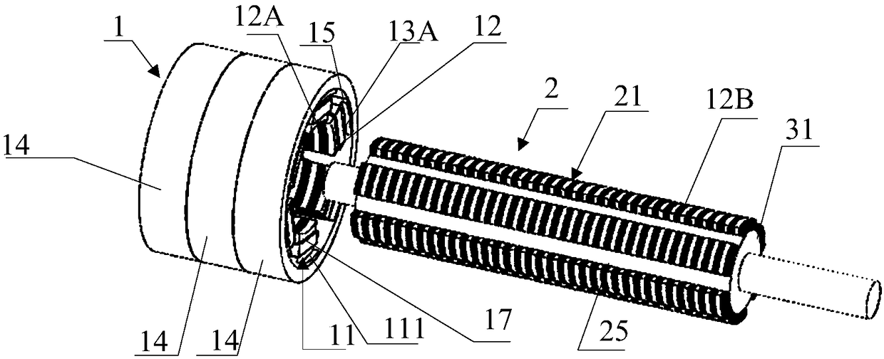
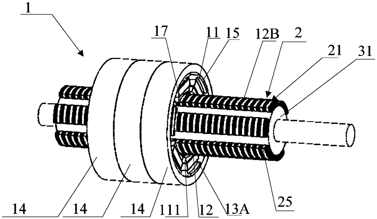
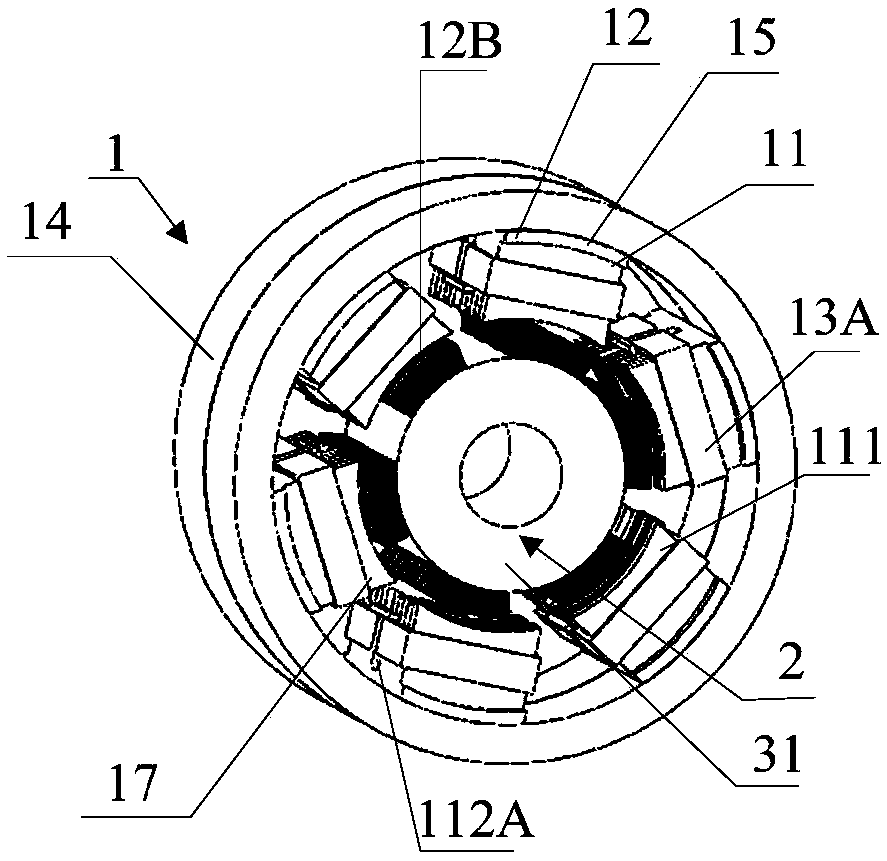
[0048] Such as figure 2 As shown, the present invention provides a cylindrical linear motor, which includes: a primary structure 1, a secondary structure 2, multiple sets of thirteenth salient pole structures 11, multiple third permanent magnets 12A, multiple The fourth permanent magnet 12B, a plurality of first windings 13A and a plurality of second windings 13B, the primary structure 1 and the secondary structure 2 are both cylindrical, and the primary structure 1 is surrounded by the secondary The outer side of the structure 2, the secondary structure 2 is arranged coaxially with the primary structure 1, and a plurality of the fourth permanent magnets 12B are installed on the outer wall of the secondary structure 2; the thirteenth salient pole structure One end of 11 is installed on the inner wall of the primary structure 1, and a plurality of the third permanent magnets 12A, a plurality of first windings 13A and a plurality of second windings 13B are all installed in a pl...

Embodiment 2

[0057] Such as figure 2 and Figure 8 As shown, on the basis of Embodiment 1, the primary structure 2 of this embodiment includes: a plurality of single-phase one-unit primary components 14; wherein, the non-magnetic material acts as a magnetic isolation and fixation for the primary components of each unit The role of connection. The single-phase one-unit primary part 14 is in the shape of a hollow ring, and the inner ring wall of the single-phase one-unit primary part 14 is provided with multiple sets of the thirteenth salient pole structures 11, and multiple sets of the thirteenth salient pole structures 11 are arranged. The salient pole structures 11 are arranged at equal intervals along the circumferential direction on the inner wall of the single-phase one-unit primary part 14 .

[0058] In the process of actual production and application, the number of units of the motor can be changed according to the demand, so the number of units of the actual motor can be set to m...

Embodiment 3

[0063] Such as Figure 12 to Figure 14 As shown, on the basis of Embodiment 1, the plurality of third permanent magnets 12A and the plurality of fourth permanent magnets 12B in this embodiment are all magnetized in the radial direction.

[0064] In order to make the magnetic density in the air gap close to a sine wave, the magnetization directions of each third permanent magnet 12A and each fourth permanent magnet 12B are not completely the same, but they are all magnetized along the radial direction, and each third permanent magnet 12A and each fourth permanent magnet 12B are magnetized in the radial direction. The schematic diagram of magnetization direction of four permanent magnets 12B is as Figure 12 As shown, the lower side of the leftmost third permanent magnet 12A in the figure can be N-level, the upper side of the leftmost third permanent magnet 12A in the figure can be S-level, and the remaining third permanent magnets 12A are arranged in the same way The bottom side...


PUM


Abstract

The invention relates to a cylinder linear motor. The cylinder linear motor comprises a primary structure, a secondary structure, multiple sets of thirteenth salient pole structures, multiple third permanent magnets, multiple fourth permanent magnets, multiple first windings and multiple second windings, wherein the primary structure and the secondary structure are cylindrical structures, the primary structure is sleeved outside the secondary structure, the primary structure and the secondary structure are coaxially arranged, the multiple fourth permanent magnets are mounted on an outer wall of the secondary structure, one ends of the thirteenth salient pole structures are mounted on an inner wall of the primary structure, and the multiple third permanent magnets, the multiple first windings and the multiple second windings are mounted on the multiple sets of thirteenth salient pole structures. The windings are arranged on the static side of the primary structure, so the structure of the secondary structure is made to be simple, cost is reduced, moreover, the secondary structure is disposed in the sea water, corrosion to the magnet windings is avoided, maintenance is convenient, reliability is high, the permanent magnets used for having the auxiliary effect are all arranged on the secondary structure, and the magnetic field of the linear motor is further improved.

Description

technical field [0001] The invention relates to the technical field of direct drive wave power generation, in particular to a cylindrical linear motor. Background technique [0002] Linear motor is a transmission device that directly converts electrical energy into linear motion mechanical energy without any intermediate conversion mechanism. In the prior art, the windings and permanent magnets of the linear motor are usually arranged on the primary or secondary of the linear motor respectively, not on the side of the motor at the same time; during the motion of the linear motor, the secondary will drive the permanent magnet and the winding For reciprocating motion, the secondary is usually made of magnetically conductive material. In the state of frequent reciprocating motion, the secondary will generate a lot of heat, which will cause the permanent magnet to lose magnetism due to excessive temperature. Contents of the invention [0003] The technical problem to be solve...

Claims


Application Information

Patent Timeline
IPC IPC(8): H02K35/02H02K41/02H02K1/34
CPCH02K35/02H02K1/34H02K41/02H02K2213/03
Inventor 赵玫魏尧杨洪勇封宁君邓冠龙韩辅君徐明铭张淑宁侯典立张平刘飞周文举
Owner LUDONG UNIVERSITY
Why Eureka
Try Eureka