Output type optical amplifier automatic testing device

An automatic test device and optical amplifier technology, which is applied in the direction of optical instrument test, measuring device, machine/structural component test, etc., can solve problems such as low efficiency, reduce human error and improve test efficiency

Inactive Publication Date: 2018-08-07
杭州万隆光电设备股份有限公司
View PDF3 Cites 0 Cited by
  • Summary
  • Abstract
  • Description
  • Claims
  • Application Information

AI Technical Summary

Problems solved by technology

Using traditional manual testing methods is not only inefficient, but also causes human errors that are difficult to control

Method used


Image

  • Output type optical amplifier automatic testing device

Examples


Embodiment Construction

[0015] The technical solutions of the embodiments of the present invention will be explained and described below in conjunction with the drawings of the embodiments of the present invention, but the following embodiments are only preferred embodiments of the present invention, not all of them. Based on the examples in the implementation manners, other examples obtained by those skilled in the art without making creative efforts all belong to the protection scope of the present invention.

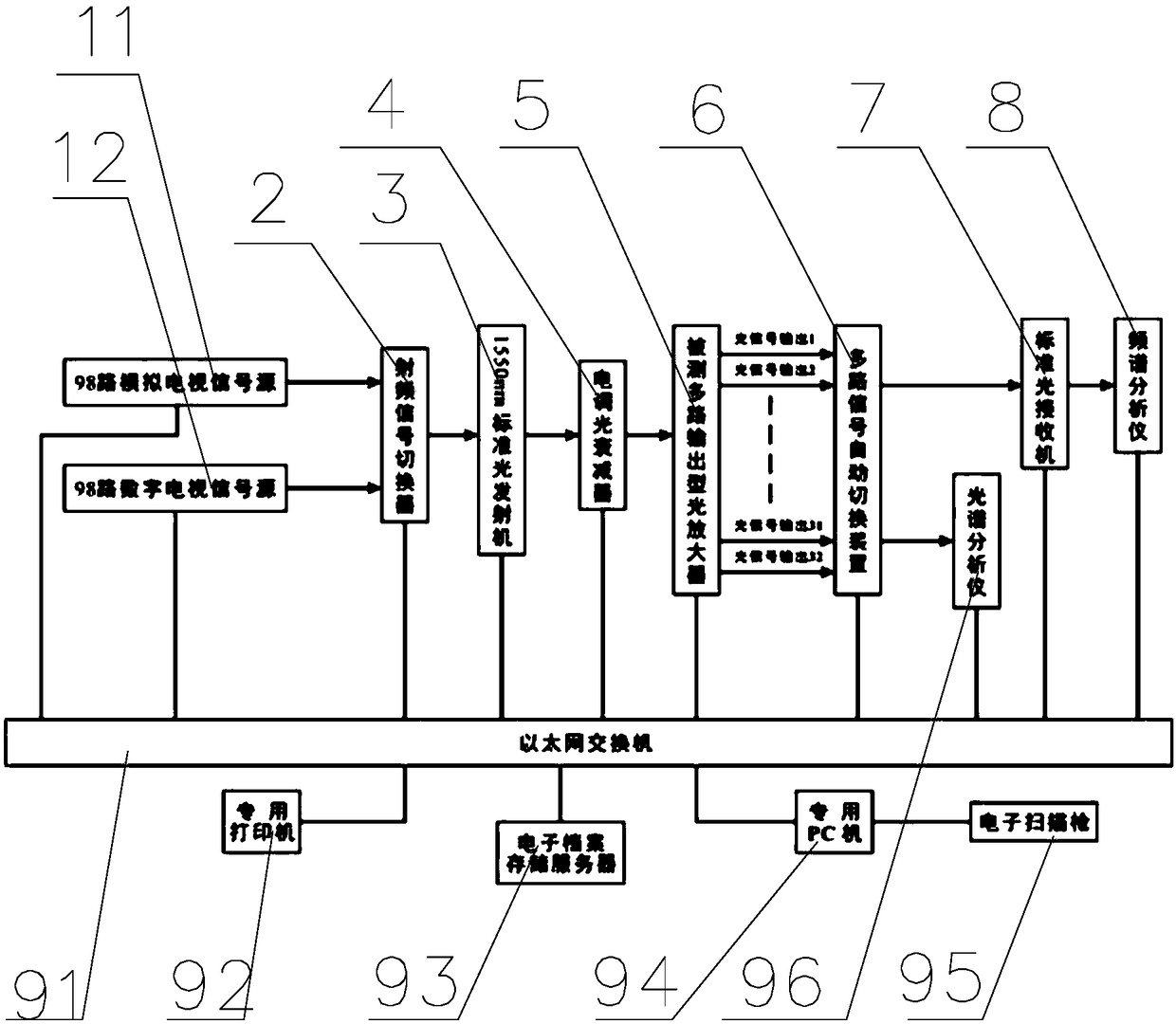
[0016] refer to figure 1 An output optical amplifier automatic test device is shown, including a radio frequency signal switcher 2, an optical transmitter 3, an electric light attenuator 4, a multi-channel output optical amplifier 5 to be tested, and an automatic switching of multiple signals Device 6, optical receiver 87, spectrum analyzer 8, radio frequency signal switcher 2 for connecting TV signal source, frequency signal switcher, optical transmitter 3, electric light attenuator 4, mult...


PUM


Abstract

The invention discloses an output type optical amplifier automatic testing device, and belongs to the photoelectric field. The output type amplifier automatic testing device comprises a radio frequency signal switcher, an optical transmitter, an electric dimming attenuator, a tested multi-path output type optical amplifier, a multi-signal automatic switching device, an optical receiver, and a spectrum analyzer; the radio frequency signal switcher is used for connecting a TV signal source; the radio frequency signal switcher, the optical transmitter, the electric dimming attenuator, the testedmulti-path output type optical amplifier, the multi-path signal automatic switching device, the optical receiver and the spectrum analyzer are connected with a computer through the Ethernet.

Description

【Technical field】 [0001] The invention relates to an output type optical amplifier automatic testing device. 【Background technique】 [0002] With the large-scale popularization of cable television "fiber-to-the-home" network, the demand for multi-output optical amplifiers in the global market is increasing exponentially. It turns out that when each multi-channel output optical amplifier leaves the factory, it is necessary to rely on manual testing of each technical parameter index of each output port to ensure the quality of the factory products. At present, the maximum number of output channels of the multi-channel output optical amplifier has reached 32 channels, and will be expanded to 64 channels in the future; each output signal needs to be tested for C / CTB, C / CSO, MER, BER, the total output optical power and noise figure 6 factory inspection indicators. Using traditional manual testing methods is not only inefficient, but also causes human errors that are difficult t...

Claims


Application Information

Patent Timeline
Patent Type & Authority Applications(China)
IPC IPC(8): H04N17/00H04N7/22G01M11/00G01J3/28
CPCG01J3/28G01M11/00H04N7/22H04N17/00H04N17/004
Inventor 许泉海朱国堂余兴洪任国瑞
Owner 杭州万隆光电设备股份有限公司
Why Eureka
Try Eureka