Improved ballistocardiogram signal system

A ballistocardiogram and signal system technology, applied in medical science, sensors, diagnostic recording/measurement, etc., can solve problems such as the inability to clearly judge heart beats, and achieve the effect of avoiding system insensitivity and improving sensitivity

Pending Publication Date: 2018-08-10
DEQING DEYI COMP CO LTD
View PDF5 Cites 3 Cited by
  • Summary
  • Abstract
  • Description
  • Claims
  • Application Information

AI Technical Summary

Problems solved by technology

Unable to clearly judge the process of heart beat

Method used


Image

  • Improved ballistocardiogram signal system
  • Improved ballistocardiogram signal system
  • Improved ballistocardiogram signal system

Examples


Embodiment 1

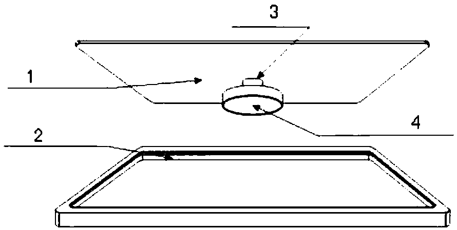
[0026] An improved ballistic cardiogram signal system, which includes a ballistic cardiogram signal collection and conduction device and an extremely low frequency micro-vibration signal sensor. The ballistic cardiogram signal collection and conduction device includes a vibration collection panel 2, a conductive sheet 3, and a support 6. Bottom plate 1. The extremely low frequency micro-vibration signal sensor 4 is installed on the bottom plate 1. The vibration collection panel 2 is installed on the bottom plate 1 through a support 6 with a certain thickness. The upper surface of the conductive sheet 3 supports the vibration collection panel On the bottom surface of 2, the lower surface of the conductive sheet 3 is against the center position of the upper part of the extremely low frequency micro-vibration signal sensor 4. Such as image 3 with Figure 4 As shown, the vibration collecting panel 2 and the bottom plate 1 are kept substantially parallel. Except for the contact part...

Embodiment 2

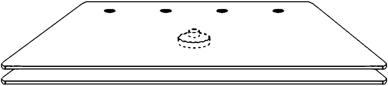
[0031] Such as Figure 4 with Image 6 As shown, the vibration collection panel 2 provided by this embodiment and the bottom plate 1 are circular in shape and match in size. The bottom plate 1 is provided with a cylindrical support 6 with a height, and the support 6 is provided with a Mounting hole, the vibration collection panel 2 is provided with a mounting hole 5, through the two opposite mounting holes through fasteners, in this way, the vibration collection panel 2 and the bottom plate 1 are fixed at points, which also forms an internal support point. 压板体。 Press plate body.

[0032] In addition, the bottom plate 1 must have good rigidity. The material can be steel plate, carbon fiber board, glass fiber board, etc. When the material is not sufficiently rigid, it can be solved by increasing the thickness of the plate. The requirements of the vibration collection panel are the same as the original patent CN105726036A, that is, the vibration collection panel is a creep-resistant...

Embodiment 3

[0035] Such as Figure 4 with Image 6 As shown, the vibration collection panel 2 provided by this embodiment is integrated with the bottom plate 1. Through 3D printing or machine tool processing, the whole plate is processed into the shape of "Semi-I", but the extremely low frequency The micro-vibration signal sensor 4 is embedded between the upper and lower layers, and the effect of Embodiment 1 can also be achieved.


PUM


Abstract

The invention provides an improved ballistocardiogram signal system. The system comprises a ballistocardiogram signal acquisition and conduction device and an extremely low-frequency micro-vibration signal sensor, wherein the ballistocardiogram signal acquisition and conduction device comprises a vibration acquisition panel, a conduction sheet, a supporting piece and a bottom plate; except for thecontact part of the supporting piece, the other part of the acquisition panel and the bottom plate maintain suspended; the conduction sheet and the extremely low-frequency micro-vibration signal sensor form one supporting point between the vibration acquisition panel and the bottom plate; and the vibration acquisition panel and the local area of the bottom plate are fastened through the supporting piece, so that during signal acquisition, the vibration acquisition panel and the bottom plate are not loosened or displaced. The sensitivity of the ballistocardiogram signal system is greatly improved, and the conditions of signal distortion, attenuation or unstable operation are avoided.

Description

Technical field [0001] The invention belongs to the field of cardiocardiogram signal processing, and specifically relates to an improved cardiocardiogram signal system. Background technique [0002] The beating and impact of the heart can cause a series of periodic vibrations of the human body. These signals are recorded by sensitive instruments to form a waveform diagram, and then the diagnosis of human diseases by observing the waveform diagram is the origin of the cardiogram. [0003] CN105726037A, N105877758A, 105726038A, CN105651375A, CN105726036A are a percussion cardiogram conduction device, acquisition system and recorder disclosed by the applicant, [0004] Such as figure 1 As shown, CN105726036A specifically includes a ballistic cardiogram signal collection and conduction device and an extremely low frequency micro-vibration signal sensor 4, wherein the ballistic cardiogram signal collection and conduction device includes a vibration collection panel 2, a conductive sheet 3...

Claims


Application Information

Patent Timeline
Patent Type & Authority Applications(China)
IPC IPC(8): A61B5/11
CPCA61B5/1102A61B5/1126
Inventor 张健挺
Owner DEQING DEYI COMP CO LTD
Why Eureka
Try Eureka