Boring cutter with arc structure

A boring tool and arc technology, which is used in the direction of tools, cutting inserts, tool holders and other accessories for lathes. Insufficient head strength, etc., to achieve the effect of good chip removal effect, strong chip removal ability, smoothness and dimensional accuracy improvement

Inactive Publication Date: 2018-08-10
常州思智行睿精密机械有限公司
View PDF0 Cites 3 Cited by
  • Summary
  • Abstract
  • Description
  • Claims
  • Application Information

AI Technical Summary

Problems solved by technology

[0002] With the rapid development of science and technology and machinery, the processing requirements for parts in mechanical applications are getting higher and higher, and boring is a kind of inner diameter turning process that uses tools to expand holes or other circular contours. Special tools for machining holes have been widely used in the field of mechanical processing. The existing boring tools cannot fully guarantee the reasonable matching of the chip removal space and strength, and the existing boring tools can not fully guarantee the reasonable matching of chip removal space and strength. In the middle, due to vibration and other reasons, sometimes the boring tool may loosen from the tool holder, or even fall off, and the existing boring tool cannot be deformed as a whole. When boring, the boring tool and the workpiece are just in contact. When the two collide, a large impact force will be generated. At this time, the cutting edge is prone to breakage, and the cutting head of the existing boring tool is perpendicular to the direction of rotation, lacking support, so the strength of the cutting head is not enough.

Method used


Image

  • Boring cutter with arc structure
  • Boring cutter with arc structure
  • Boring cutter with arc structure

Examples


Embodiment Construction

[0017] The following will clearly and completely describe the technical solutions in the embodiments of the present invention with reference to the accompanying drawings in the embodiments of the present invention. Obviously, the described embodiments are only some, not all, embodiments of the present invention. Based on the embodiments of the present invention, all other embodiments obtained by persons of ordinary skill in the art without making creative efforts belong to the protection scope of the present invention.

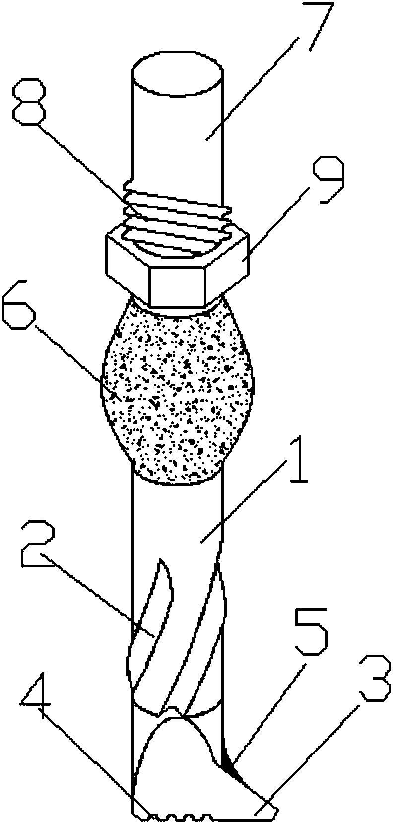
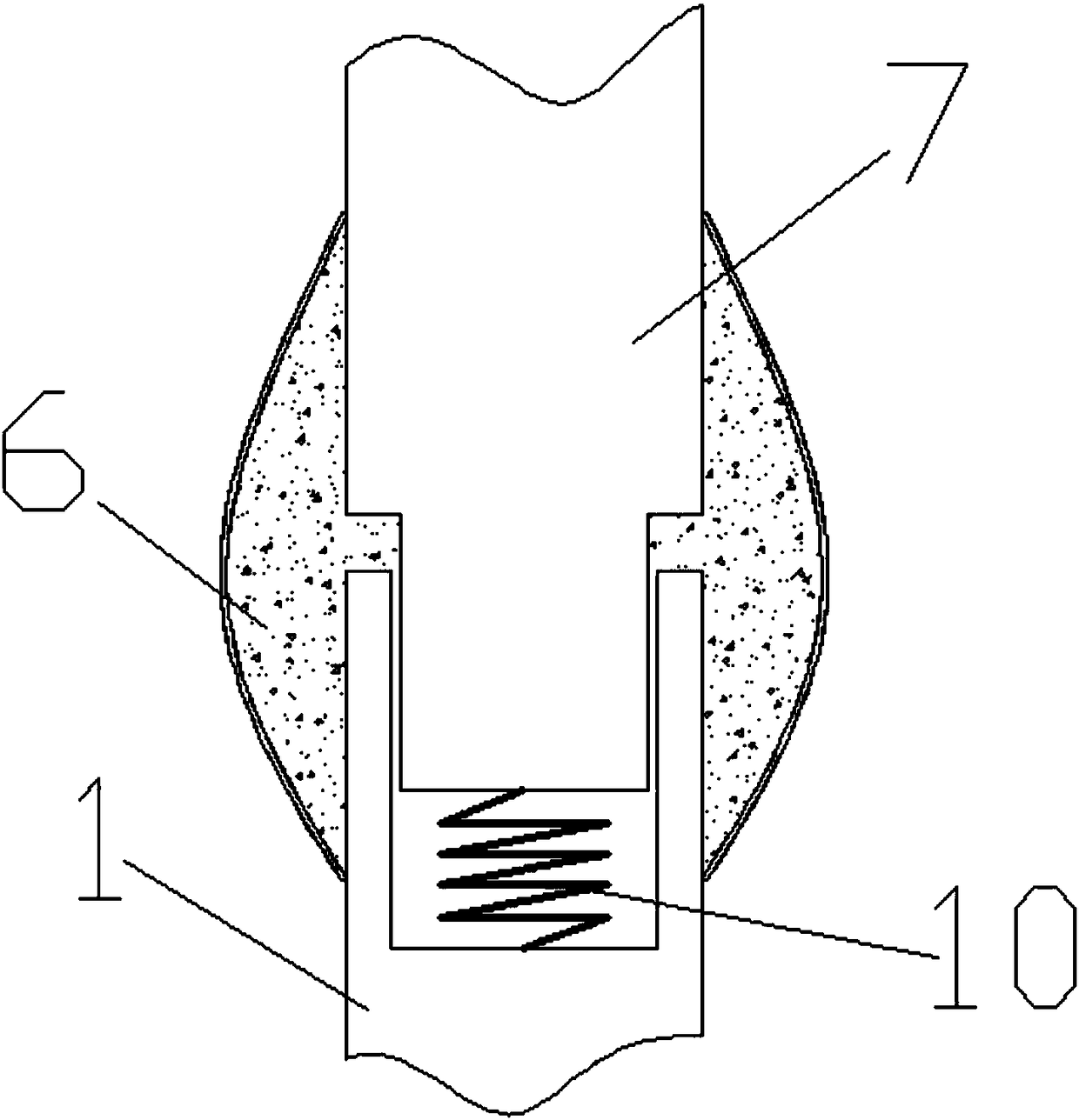
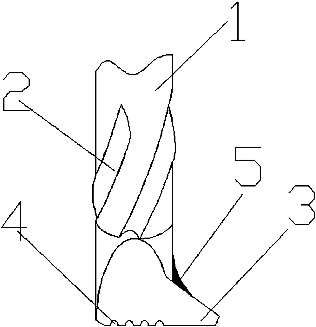
[0018] see Figure 1-4 , a boring tool with a circular arc structure, including a connecting rod 1, a chip removal groove 2, a cutter head 3, a force release port 4, a reinforcing rib 5, a protective rubber block 6, a handle 7, a thread 8, and an extrusion nut 9 and spring 10; the connecting rod 1 is provided with a chip removal groove 2, and the chip removal groove 2 is four symmetrical and its cut surface is a concave arc shape, the bottom of the chip remova...


PUM


Abstract

The invention discloses a boring cutter with an arc structure. The boring cutter comprises a connecting rod, chip removing grooves, a tool bit, pressure relief ports, reinforcing ribs, a protective rubber block, a knife handle, threads, an extrusion nut and a spring. The boring cutter with the arc structure has the beneficial effects that the bottom of the tool bit is uniformly provided with a plurality of inward-concave arc-shaped pressure relief ports, and the impact force borne by the tool bit when boring hole is carried out and when the tool bit makes contact with a workpiece can be reasonably dispersed, the vibration of the tool bit is reduced, so that the process of the hole boring is stable; the connecting part between the connecting rod and the tool bit is fixedly provided with thereinforcing ribs with the arc surfaces on the surfaces, so that the pressure borne by the tool bit can be dispersed to the connecting rod through the reinforcing ribs, and the stress strength of thetool bit can be improved; the number of the chip removal grooves are symmetric four, and the tangent plane of each chip removal groove is of the inward-concave arc shape which is provided with a largechip removal space, so that the chip removal effect of the boring cutter is good; the knife handle can move up and down inside the connecting rod, the knife handle is provided with a certain deformability, so that the large impact force cannot be generated between the tool bit and the workpiece when the tool bit is just in contact with the workpiece.

Description

technical field [0001] The invention relates to a boring cutter with an arc structure, in particular to a boring cutter with an arc structure, which belongs to the field of mechanical processing. Background technique [0002] With the rapid development of science and technology and machinery, the processing requirements for parts in mechanical applications are getting higher and higher, and boring is a kind of inner diameter turning process that uses tools to expand holes or other circular contours. Special tools for machining holes have been widely used in the field of mechanical processing. The existing boring tools cannot fully guarantee the reasonable matching of the chip removal space and strength, and the existing boring tools can not fully guarantee the reasonable matching of chip removal space and strength. In the middle, due to vibration and other reasons, sometimes the boring tool may loosen from the tool holder, or even fall off, and the existing boring tool canno...

Claims


Application Information

Patent Timeline
Patent Type & Authority Applications(China)
IPC IPC(8): B23B27/00
CPCB23B27/00B23B2200/328B23B2250/16
Inventor 刘阳河王永齐
Owner 常州思智行睿精密机械有限公司
Why Eureka
Try Eureka