Glue injecting assembly used on injecting device as well as injection molding machine and injection molding method

An injection device and injection technology, which are applied to injection components, injection molding machines and injection molding fields, can solve problems such as increased manufacturing costs and waste of plastic raw materials, and achieve the effects of reducing flow time, saving raw materials, and fast filling speed.

Pending Publication Date: 2018-08-10
SHENZHEN GANGYUAN MICRO KEY TECH CO LTD
View PDF0 Cites 1 Cited by
  • Summary
  • Abstract
  • Description
  • Claims
  • Application Information

AI Technical Summary

Problems solved by technology

When using this injection molding machine to inject tact switches (such as figure 1 As shown), in general, after the injection device is in contact with the sprue sleeve of the mold installed on the mold clamping device, the plastic in the molten state is directly injected into the cavity through the runner on the mold, so that a large number of The plastic residue in the molten state solidifies in the runner to form waste, which causes waste of plastic raw materials and increases manufacturing costs

Method used


Image

  • Glue injecting assembly used on injecting device as well as injection molding machine and injection molding method
  • Glue injecting assembly used on injecting device as well as injection molding machine and injection molding method
  • Glue injecting assembly used on injecting device as well as injection molding machine and injection molding method

Examples


Embodiment Construction

[0050] The present invention will be described in further detail below in conjunction with the accompanying drawings.

[0051] This specific embodiment is only an explanation of the present invention, and it is not a limitation of the present invention. Those skilled in the art can make modifications to this embodiment as required after reading this specification, but as long as they are within the rights of the present invention All claims are protected by patent law.

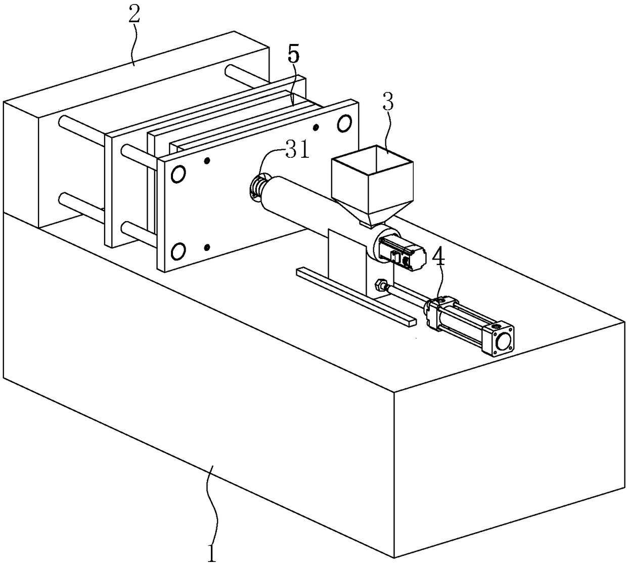
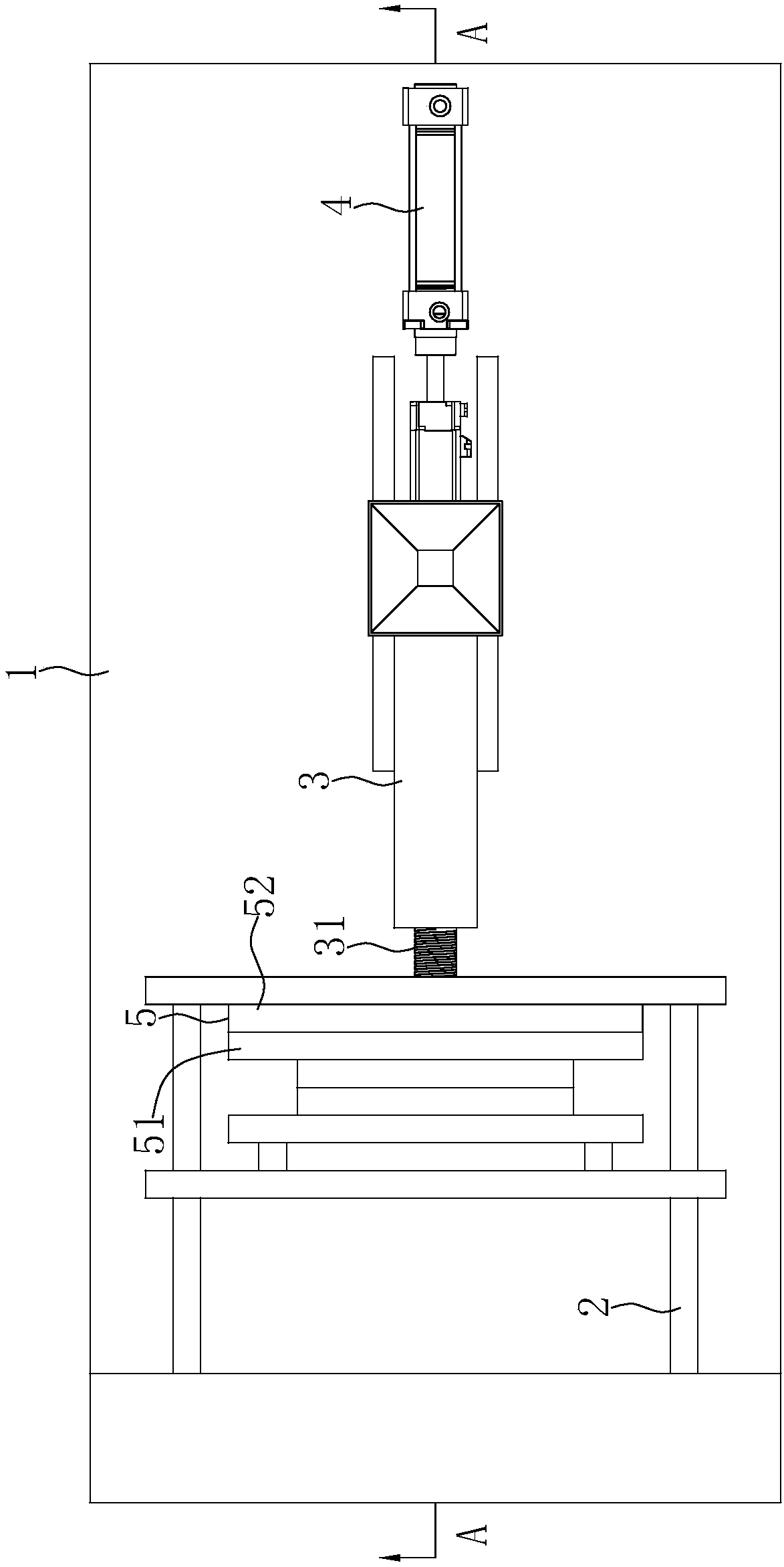
[0052] This embodiment relates to an injection molding machine, such as figure 2 As shown, it mainly includes: a body 1 , a mold clamping device 2 , an injection device 3 and a driving device 4 .

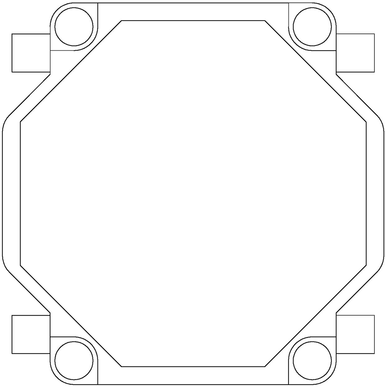
[0053] combine figure 1 As shown, the mold clamping device 2 is arranged on the fuselage 1, and the mold clamping device 2 is used to install the injection mold 5 and drive the injection mold 5 to open and close the mold. The injection device 3 is arranged on the body 1 and is provided with a plastic injection a...


PUM


Abstract

The invention relates to a glue injecting assembly used on an injecting device. The glue injecting assembly comprises a middle nozzle, a spray nozzle, a temperature sensor and a first heating coil, wherein the middle nozzle is arranged on the injecting device in a bulged mode; the spray nozzle is arranged on the middle nozzle, can be detachably assembled with the middle nozzle, passes through a fixed molding board and a fixed mould fixed plate of an injection mould for injecting rubber under a molten state into a mould cavity of the injection mould after a discharge end reaches a correspondingposition on a pouring gate on a fixed mould of the injection mould; the temperature sensor is arranged on the spray nozzle and is connected with an external controller; and the first heating coil iswound on the outer surface of the spray nozzle and is electrically connected with the external controller. When the glue injecting assembly injects, waste, in a runner, of rubber is reduced, flowing time, in the runner, of the rubber is shortened, and speed of filling the mould cavity with the rubber is increased through the spray nozzle arranged on the middle nozzle, so that the glue injecting assembly has the advantages of saving raw materials, reducing cost, being short in mould filling time and being high in filling speed.

Description

technical field [0001] The invention relates to the technical field of injection molding equipment, in particular to a plastic injection component used on an injection device, an injection molding machine and an injection molding method. Background technique [0002] Injection molding machine is also known as injection molding machine or injection machine. It is the main molding equipment for making thermoplastics or thermosetting plastics into various shapes of plastic products using injection molds. Among them, injection molds mainly include: panel, fixed mold fixed plate, fixed template, fixed mold, moving mold, moving template, Moving mold fixed plate, pad, sprue, thimble, thimble plate, guide post and guide sleeve, etc. Injection molding machines are divided into vertical, horizontal and all-electric. The function of the injection molding machine is to heat the plastic to a molten state and apply high pressure to it to make it inject and fill the mold cavity, and the ...

Claims


Application Information

Patent Timeline
IPC IPC(8): B29C45/03B29C45/20
CPCB29C45/03B29C45/20
Inventor 胡双元盛黎明胡志敏
Owner SHENZHEN GANGYUAN MICRO KEY TECH CO LTD
Why Eureka
Try Eureka