Swing cylinder drive structure for industrial carrying manipulators

A transmission structure and swing cylinder technology, applied in the field of manipulators, can solve problems such as high sealing requirements, difficult processing, and complex structures, and achieve the effects of good sealing, small size, and simplified manipulator structure

Inactive Publication Date: 2018-08-10
SHAANXI LAIFU TECH DEV CO LTD
View PDF0 Cites 0 Cited by
  • Summary
  • Abstract
  • Description
  • Claims
  • Application Information

AI Technical Summary

Problems solved by technology

The swing cylinder device used by the existing manipulator has a complex structure, difficult processing, high sealing requirements, and easy internal leakage

Method used


Image

  • Swing cylinder drive structure for industrial carrying manipulators

Examples


Embodiment Construction

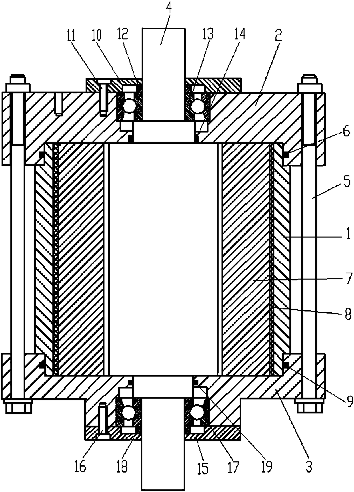
[0013] Attached below figure 1 Embodiments of the present invention are described.

[0014] Swing cylinder transmission structure for industrial handling manipulator, such as figure 1 As shown, it includes a swing cylinder cylinder 1, the front end of the swing cylinder cylinder 1 is sealed and connected with a swing cylinder front end cover 2, and a front sealing ring I6 is provided at the contact between the swing cylinder front end cover 2 and the front end of the swing cylinder cylinder 1, The rear end of the swing cylinder barrel 1 is sealed and connected with a swing cylinder rear end cover 3 , and a rear sealing ring I9 is ​​provided at the contact between the swing cylinder rear end cover 3 and the rear end of the swing cylinder barrel 1 .

[0015] An output shaft 4 is supported in the cylinder barrel 1 of the swing cylinder, and the front end of the output shaft 4 is supported in the front end cover 2 of the swing cylinder through a front bearing 13 and extends outsi...


PUM


Abstract

Provided is a swing cylinder drive structure for industrial carrying manipulators. The swing cylinder drive structure comprises a swing cylinder barrel, a front swing cylinder end cover is in sealed connection with the front end of the swing cylinder barrel, and a rear swing cylinder end cover is in sealed connection with the rear end of the swing cylinder barrel. An output shaft is supported in the swing cylinder barrel, the front end of the output shaft is supported in the front swing cylinder end cover through a front bearing and extends out of the front swing cylinder end cover, and the rear end of the output shaft is supported in the rear swing cylinder end cover through a rear bearing and extends out of the rear swing cylinder end cover. The part, inside the swing cylinder barrel, ofthe output shaft is sleeved with a shaft sleeve, and a sealing strip is arranged between the shaft sleeve and the swing cylinder barrel. The swing cylinder drive structure for the industrial carryingmanipulators is mainly composed of the swing cylinder barrel, the front swing cylinder end cover, the rear swing cylinder end cover and the output shaft, thereby being simple, easy to machine and manufacture, small in size, low in weight, beneficial for simplifying the structures of the manipulators, and particularly suitable for arm rotation of the small and medium sized manipulators. Meanwhile,as the swing cylinder drive structure is simple, the leakproof structure is easy to implement, good air tightness is achieved, and internal leakage inside a cylinder body is effectively prevented.

Description

technical field [0001] The invention belongs to the technical field of manipulators, and in particular relates to a swing cylinder transmission structure for an industrial handling manipulator. Background technique [0002] The main function of industrial manipulators is to realize human actions mechanically. It has the characteristics of independent control system, variable program, and flexible and diverse actions. The manipulator is mainly composed of a hand and a movement mechanism. The hand is a part used to grasp the workpiece. The movement mechanism can make the hand complete various rotations, movements or compound movements to achieve predetermined actions, change the position and position of the grasped object. posture. The main function of the swing cylinder as the manipulator is to drive the hand of the manipulator to perform rotary motion. One end of it is connected to the hand of the manipulator through a connecting piece, and the other end is connected to the...

Claims


Application Information

Patent Timeline
Patent Type & Authority Applications(China)
IPC IPC(8): F15B15/04F15B15/20
CPCF15B15/04F15B15/20
Inventor 杨晓东
Owner SHAANXI LAIFU TECH DEV CO LTD
Why Eureka
Try Eureka