
A molten salt reactor core

A molten salt reactor and core technology, applied in the field of molten salt reactor core, can solve the problems of affecting heat transfer and neutron characteristics, breakage of corner fracture components, low fuel utilization value, etc., so as to reduce the irradiation fluence rate , reduce the deformation stress, and facilitate the effect of heat transfer

Active Publication Date: 2019-10-15
SHANGHAI INST OF APPLIED PHYSICS - CHINESE ACAD OF SCI
View PDF7 Cites 0 Cited by
  • Summary
  • Abstract
  • Description
  • Claims
  • Application Information

AI Technical Summary

Problems solved by technology

[0007] The technical problem to be solved by the present invention is to overcome the obvious deformation of the corner contact between the molten salt reactor core assembly and the assembly in the prior art, which will cause the corner to break and the assembly to be damaged, and the core assembly and assembly to be damaged. The narrow gaps between them are not connected with the molten salt channel, which will form a dead zone and affect the heat transfer and neutron characteristics. The molten salt surface area of ​​the plate-type component is the largest, resulting in low fuel utilization value and weak space self-shielding effect on U238. Provide molten salt reactor core

Method used


Image

  • A molten salt reactor core
  • A molten salt reactor core
  • A molten salt reactor core

Examples


Embodiment 1

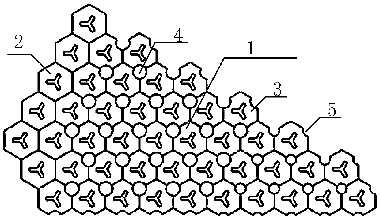
[0076] The top view of the molten salt reactor core in this embodiment is shown in figure 1 , which includes an active area 1 and a reflective layer 2, the reflective layer 2 covers the active area 1, and the active area 1 is assembled from an array of fuel assemblies 3;

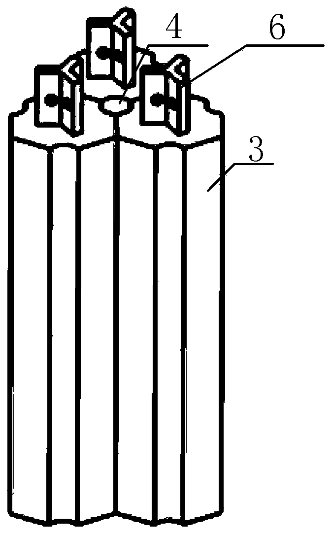
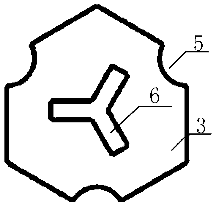
[0077] Wherein, the fuel assembly 3 is a chamfered regular hexagonal prism, the chamfered positions of the three fuel assemblies 3 are opposite, and the gap 5 forms a molten salt channel 4; the volume of the molten salt channel 4 accounts for 5% of the volume of the active area 1; the active area 1 is divided into a central area and an edge area, the volume ratio of the central area to the edge area is 1 / 14, and the volume of the single molten salt channel 4 in the central area accounts for 40% of the volume of the single molten salt channel 4 in the edge area.

[0078] In this embodiment, the assembly of the reflective layer 2 is used in conjunction with the fuel assembly 3 in the active area 1, and the ass...

Embodiment 2

[0097] The assembly of the fuel assembly 3 and the reflection layer 2 of the molten salt reactor core of this embodiment is a regular quadrangular prism, wherein the structure of the fuel assembly 3 is as follows Figure 17 shown. The volume of the molten salt channel 4 accounts for 6% of the volume of the active area 1 . The side edges of the regular quadrangular prism are cut by the outer arc surface, and the length of the bottom surface of the cut cuboid is 2 cm. The distance across sides of the cuboid is 20cm, the height of a single cuboid is 1m, and there are 5 layers in total, and the thickness of the reflective layer 2 is 30cm. The arrangement, engagement and fixation of the components of the fuel assembly 3 and the reflective layer 2 in this embodiment are similar to those in the first embodiment.

Embodiment 3

[0099] The assembly of the fuel assembly 3 and the reflection layer 2 of the molten salt reactor core of this embodiment is a regular quadrangular prism, wherein the structure of the fuel assembly 3 is as follows Figure 18 As shown, the side edges of the cuboid are cut by the inner arc surface, and the side length of the bottom surface of the cut regular prism is 5.5 cm. The volume of the molten salt channel 4 accounts for 6% of the volume of the active area 1 . The distance across sides of the regular quadrangular prism is 20cm, the height of a single cuboid is 1m, and there are 5 layers in total, and the thickness of the reflective layer 2 is 30cm. The arrangement, engagement and fixation of the components of the fuel assembly 3 and the reflective layer 2 in this embodiment are similar to those in the first embodiment.


PUM


Abstract

The invention discloses a reactor core of a molten salt reactor. The reactor core of the molten salt reactor comprises an active region and a reflecting layer, wherein the reflection layer covers theactive region; the active region is formed by fuel assemblies through array assembling; the volume of the active region molten salt passage accounts for 2 to 25 percent of the volume of the active region; the active region comprises a center region and an edge region; the volume ratio of the center region to the edge region is 1 / 15 to 1 / 8; the volume of the single molten salt passage of the centerregion accounts for 40 to 50 percent of the volume of the single molten salt passage of the edge region; the cut edge is the arc cut side edge. The molten salt passage of the reactor core of the molten slat reactor is positioned at the side edge position of the fuel assembly; the space self shielding effect regulation range is large; the deformation stress caused by radiation can be reduced; a narrow seam and the molten salt passage are communicated so that the reactor core molten salt can realize the transverse flow mixing; the heat transfer is facilitated; a dead region is avoided; the fastneutron radiation rate of graphite in the reactor core center region is reduced; the service life of the reactor core is prolonged; opening collecting structures at the two ends of the assembly can realize the flow rate distribution regulation; the fast neutron injection quantity of the upper and lower cavity alloy is reduced.

Description

technical field [0001] The invention relates to the field of nuclear reactor engineering design, in particular to a molten salt reactor core. Background technique [0002] As the fourth-generation nuclear reactor, molten salt reactor has the advantages of economy, safety, sustainability, and non-proliferation. The fuel for molten salt reactors is in liquid form, and the core moderator is a graphite component. [0003] The design of component structures has a significant impact on the reactor fuel cycle. The volume ratio of the formed molten salt channel to the component directly affects the moderation state of the molten salt reactor, and the equivalent diameter of the formed molten salt channel directly affects the spatial self-shielding effect of the fuel. A good component structure should cover all ranges of molten salt volume fractions and equivalent diameters. [0004] Irradiation contraction and expansion of graphite components is also one of the key issues that nee...

Claims


Application Information

Patent Timeline
Patent Type & Authority Patents(China)
IPC IPC(8): G21C3/32G21C3/54
CPCG21C3/32G21C3/54Y02E30/30
Inventor 朱贵凤邹杨康旭忠戴叶周波严睿邹春燕
Owner SHANGHAI INST OF APPLIED PHYSICS - CHINESE ACAD OF SCI
Learn More