
Fluid-cooled heat sink and embedded fluid-cooled heat sink type lead-acid storage battery

A lead-acid battery, liquid cooling technology, applied in lead-acid battery, lead-acid battery construction, secondary battery and other directions, can solve the problems of battery life reduction, voltage attenuation, high cost, improve energy density, improve vibration resistance sex, small footprint effect

Pending Publication Date: 2018-08-10
钱月萍
View PDF8 Cites 0 Cited by
  • Summary
  • Abstract
  • Description
  • Claims
  • Application Information

AI Technical Summary

Problems solved by technology

[0009] The performance of lead-acid batteries is greatly affected by the ambient temperature. When the ambient temperature is high, the battery temperature is 40°C, and the battery is continuously charged for 500 hours, and the water loss is at most 1g / AH. In an environment of 75°C, under the same conditions, the water loss can reach 4g / AH. AH, taking the 60AH of an ordinary car as an example, the water loss of each battery after charging reaches 240g, which is 4 times the water consumption at 40°C, and the life of the battery is significantly reduced.
[0010] The charging and discharging efficiency is low in low temperature environment, which makes it difficult to start the car. Generally, the resistance of sulfuric acid with a concentration of 25% is 160.6×10 at +10°C. 4 Ω·m, and at -10°C, the resistance increases to 250×10 4 Ω·m, while the viscosity increases from 2.01 to 3.82, resulting in a 30% drop in battery charge and discharge capacity, and the capacity drops to 60% at -20°C
[0011] Some vehicles put the battery in the trunk to control the battery temperature, but the line is long, the cost is high, and the voltage decays; in the communication field, in order to meet the long-life requirements, air-conditioning equipment is usually equipped to cool the lead-acid battery, but the efficiency is low

Method used


Image

  • Fluid-cooled heat sink and embedded fluid-cooled heat sink type lead-acid storage battery
  • Fluid-cooled heat sink and embedded fluid-cooled heat sink type lead-acid storage battery
  • Fluid-cooled heat sink and embedded fluid-cooled heat sink type lead-acid storage battery

Examples


Embodiment Construction

[0037] Below in conjunction with accompanying drawing and embodiment the patent of the present invention is described further. The embodiments described with reference to the drawings are exemplary only for explaining the present invention and should not be construed as limiting the present invention.

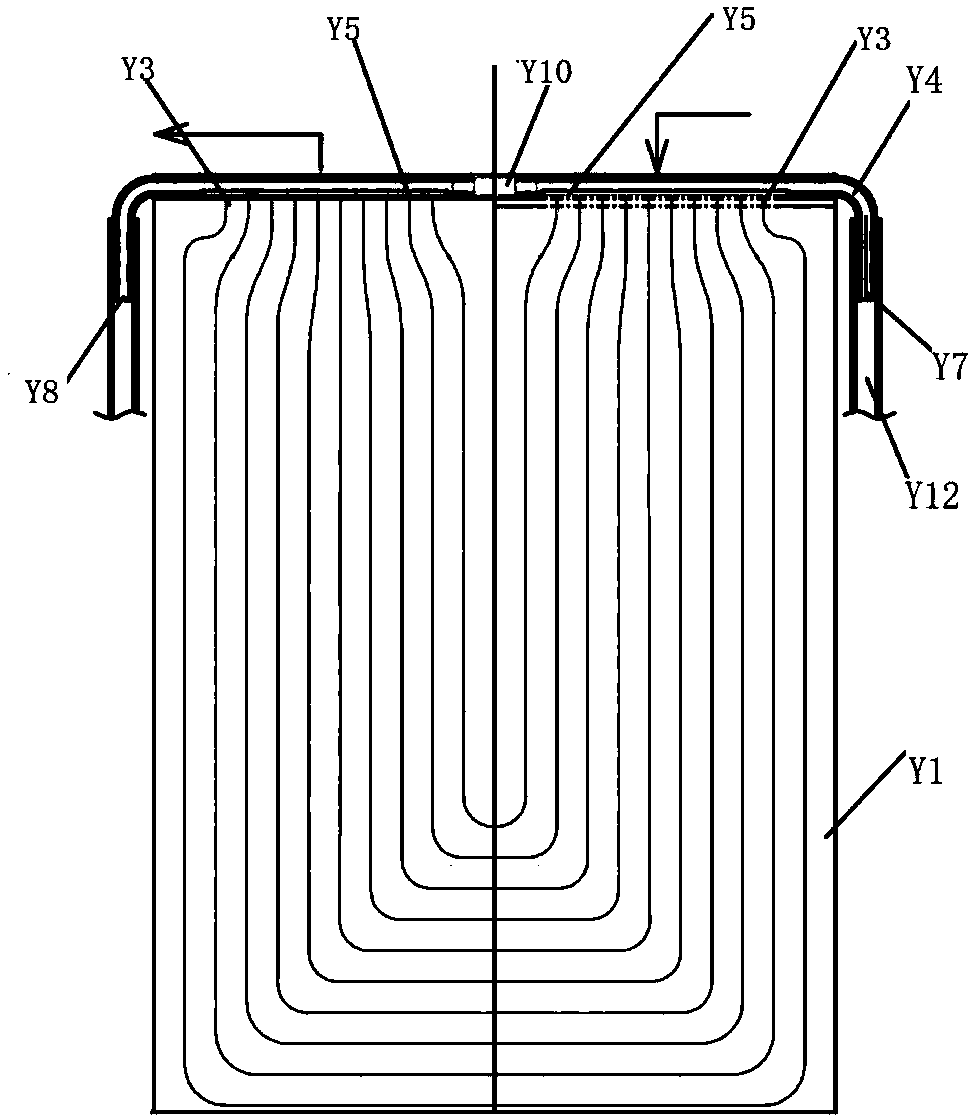
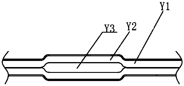
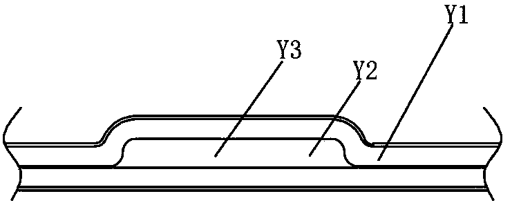
[0038] Such as figure 1 , figure 2 with image 3As shown, in this embodiment, a plurality of through grooves Y2 are punched out by stamping the aluminum sheet Y1. The end and the tail end are respectively arranged at the two ends of the Y1 side of the aluminum sheet, and a semicircle shape is punched out on the Y1 side of the aluminum sheet, and the concave-convex direction of the semicircle is consistent with the concave-convex direction of the through groove Y2; the liquid of this embodiment The cooling fin is formed by bonding two pieces of aluminum sheet Y1 with the above-mentioned structure. Two through grooves Y2 are arranged oppositely and their inner surfaces are gl...


PUM

PropertyMeasurementUnit
thicknessaaaaaaaaaa
thicknessaaaaaaaaaa

Abstract

The invention discloses a fluid-cooled heat sink and an embedded fluid-cooled heat sink type lead-acid storage battery. The embedded fluid-cooled heat sink type lead-acid storage battery comprises a storage battery main body, a separator and a fluid-cooled heat sink body, wherein the separator is arranged inside the storage battery main body; the fluid-cooled heat sink body is arranged in the separator; a plurality of fluid flow channels used for circulating fluid and an aluminum tube serving as the water inlet / outlet of the fluid flow channels are arranged on the fluid-cooled heat sink body;the aluminum tube is positioned at the bottom of the storage battery main body; the fluid-cooled heat sink body is parallel to the polar plate surface on the storage battery main body; the fluid-cooled heat sink body is isolated from acid liquor in the lead-acid storage battery by virtue of an insulating layer in the separator.

Description

technical field [0001] The invention relates to a liquid-cooled heat sink and a lead-acid battery embedded with the liquid-cooled heat sink, belonging to the technical field of lead-acid batteries. Background technique [0002] The invention relates to lithium battery heat management technology. Lithium batteries include hard square lithium batteries, soft-pack lithium batteries, and cylindrical lithium batteries; liquid-cooled heat sinks also refer to liquid-cooled heat dissipation. The liquid substance in the battery corresponds to air cooling, which belongs to the active high-efficiency heat dissipation technology; heat dissipation refers to cooling and heating, which can control the temperature of the battery so that it can work at a suitable temperature. [0003] At present, the thermal management of lithium batteries is divided into: natural cooling, air-cooled heat dissipation and water-cooled heat dissipation; natural cooling does not have any heat dissipation compon...

Claims


Application Information

Patent Timeline
Patent Type & Authority Applications(China)
IPC IPC(8): H01M10/613H01M10/615H01M10/6555H01M10/6557H01M10/6568H01M10/663H01M10/66H01M10/653H01M10/12
CPCH01M10/12H01M10/613H01M10/615H01M10/653H01M10/6555H01M10/6557H01M10/6568H01M10/66H01M10/663Y02E60/10Y02P70/50
Inventor 钱月萍
Owner 钱月萍
Learn More