Optical secondary module and optical module

A technology of optical sub-module and optical transmitter, which is applied in the field of optical communication, can solve the problems of poor heat dissipation of DFB lasers and achieve good heat dissipation effect

Inactive Publication Date: 2018-08-10
HISENSE BROADBAND MULTIMEDIA TECH
View PDF6 Cites 13 Cited by
  • Summary
  • Abstract
  • Description
  • Claims
  • Application Information

AI Technical Summary

Problems solved by technology

[0008] In order to solve the problem of poor heat dissipation of the DFB laser existing in ...

Method used


Image

  • Optical secondary module and optical module
  • Optical secondary module and optical module
  • Optical secondary module and optical module

Examples


Embodiment Construction

[0031] In order to further illustrate the principle and structure of the present invention, preferred embodiments of the present invention will now be described in detail with reference to the accompanying drawings.

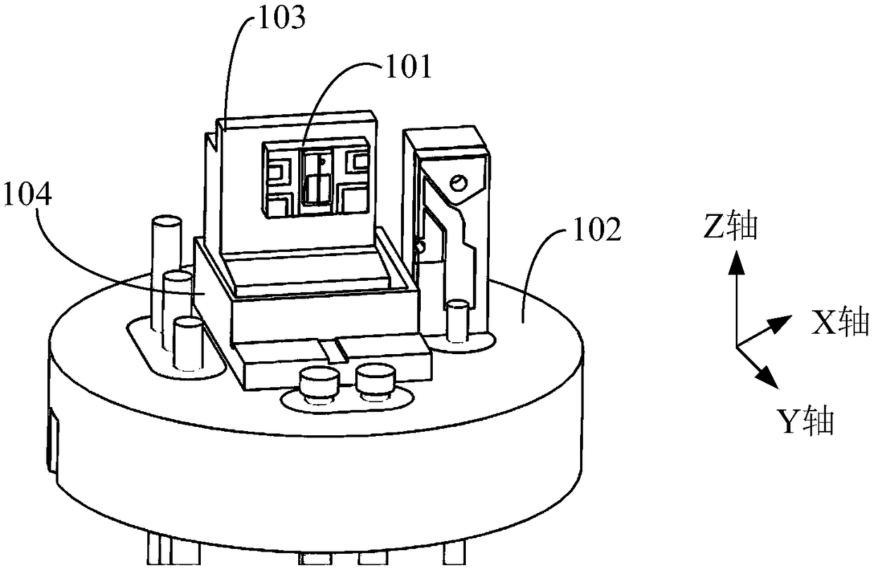
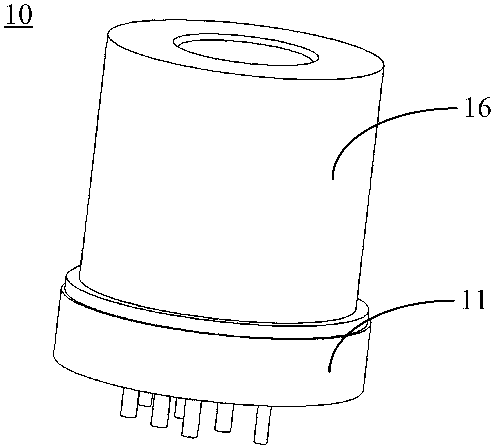
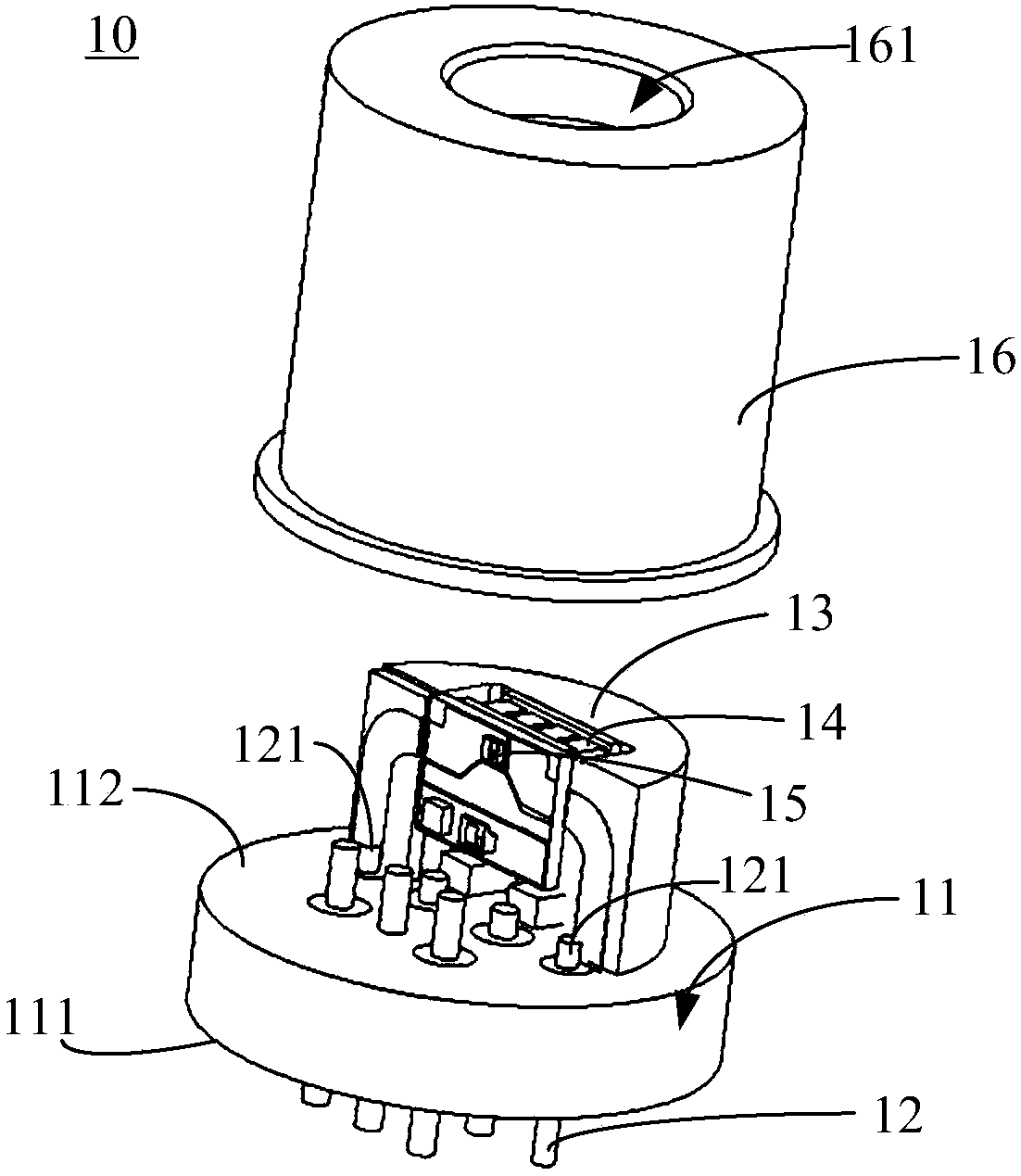
[0032] Such as figure 2 and image 3 as shown, figure 2 is a schematic diagram of the overall structure of the optical sub-module of the present invention, image 3 It is a schematic diagram of the internal structure of the optical sub-module of the present invention after removing the cap. The optical sub-module 10 includes a base body 11 , a plurality of pins 12 , a heat sink 13 , a temperature regulator 14 , a light emitter 15 and a cap 16 . The heat sink 13 is directly fixed on the base body 11 . The tube cap 16 covers the base body 11 , enclosing the heat sink 13 , the temperature regulator 14 and the light emitter 15 in a closed space enclosed by the tube cap 16 and the base body 11 . Cap 16 contains the lens and the metal piece that supports the len...


PUM


Abstract

The invention discloses an optical secondary module and an optical module. The optical module comprises at least one optical secondary module. Each optical secondary module disclosed in the inventioncomprises a base body, pins, a heat sink, a temperature regulator and an optical transmitter; the pins are mounted on the base body and run through from the bottom surface to the top surface of the base body; the heat sink is mounted on the top surface of the base body, and a groove is formed in one side, towards the pins, of the heat sink; and the temperature regulator is positioned in the grooveof the heat sink. One heat exchange surface of the temperature regulator is laminated with the inner wall of the groove, and the optical transmitter is arranged on the other heat exchange surface ofthe temperature regulator so as to ensure efficient heat transfer between the optical transmitter and the temperature regulator. By virtue of the optical secondary module and the optical module disclosed in the invention, the heat dissipation effect of the optical transmitter can be improved.

Description

technical field [0001] The invention relates to the field of optical communication, in particular to an optical sub-module and an optical module. Background technique [0002] The optical module is used for photoelectric conversion in optical communication. The optical module usually includes one or more optical sub-modules. The optical sub-module can be an optical transmitting sub-module, an optical receiving sub-module or an optical transmitting and receiving sub-module. [0003] Lasers are an important optoelectronic device in optical submodules. DFB (Distributed Feedback Laser) laser (distributed feedback laser) is widely used in optical communication because of its good monochromaticity (ie spectral purity). [0004] With the development of science and technology, the transmission rate of optical modules is getting higher and higher. Correspondingly, the transmission rate of the laser is also continuously improved. With the maturity of the international telecommunica...

Claims


Application Information

Patent Timeline
IPC IPC(8): H01S5/12H01S5/024H01S5/02315H01S5/0233
CPCH01S5/02415H01S5/02476H01S5/12H01S5/0233H01S5/02315H01S5/02212H01S5/06226H01S5/023H01S5/0235H01S5/02345H01S5/0231
Inventor 王果果
Owner HISENSE BROADBAND MULTIMEDIA TECH
Why Eureka
Try Eureka