Nut cover die machining jig and nut cover die machining machine tool

A technology for processing machine tools and mold sets, which is applied in the field of processing molds, can solve problems such as side angle errors of nut sleeve molds, achieve the effects of reducing processing time, reducing cutting volume, and improving processing efficiency

Pending Publication Date: 2018-08-14
周志容
View PDF9 Cites 1 Cited by
  • Summary
  • Abstract
  • Description
  • Claims
  • Application Information

AI Technical Summary

Problems solved by technology

[0004] The purpose of the present invention is to provide a nut sleeve die processing jig to solve the technical problem of the side angle error of processing the nut sleeve die in the prior art

Method used


Image

  • Nut cover die machining jig and nut cover die machining machine tool
  • Nut cover die machining jig and nut cover die machining machine tool
  • Nut cover die machining jig and nut cover die machining machine tool

Examples


Embodiment 1

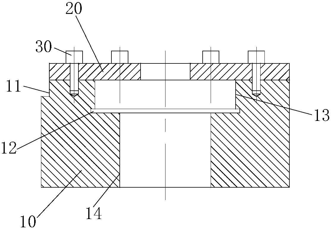
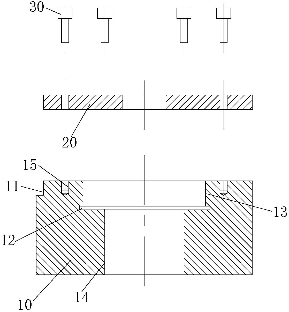
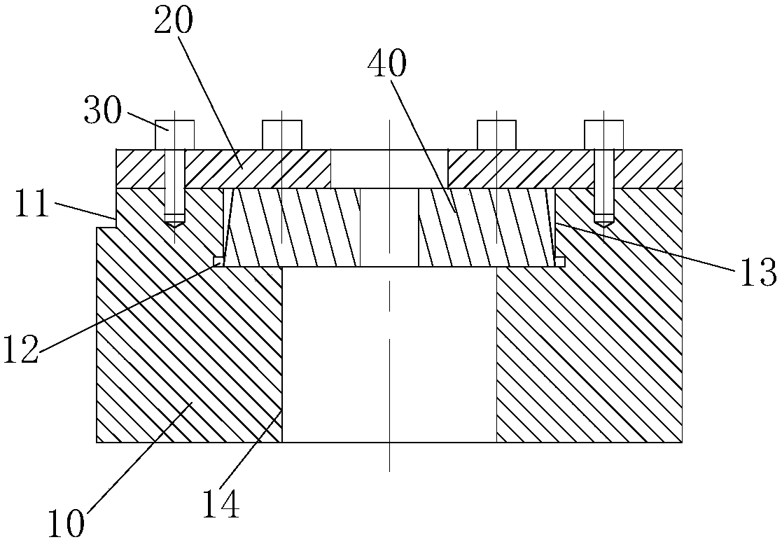
[0036] Such as Figure 1-Figure 4 As shown, the present embodiment provides a nut sleeve mold processing jig, including a fixture seat 10 and a fixture cover 20, the fixture cover 20 is detachably installed on the fixture seat 10, the fixture seat 10 has a first clamping surface, and a second One clamping surface is the inner end surface of the first hole on the surface of the clamp seat 10 , the clamp cover 20 has a second clamping surface, and the first clamping surface and the second clamping surface are used to clamp the nut cover mold 40 .

[0037] The beneficial effects of the nut sleeve mold processing fixture of the present invention are:

[0038] The nut cover mold processing jig can clamp the nut cover mold 40 from the two end faces of the nut cover mold 40 by setting the first clamping surface of the clamp seat 10 and the second clamping surface of the clamp cover 20 , can facilitate the center of the nut sleeve mold 40 to be processed with corresponding geometric ...

Embodiment 2

[0055] Such as Figure 5 As shown, the difference between this embodiment and Embodiment 1 is that the clamp cover 20 has an inner hole, and the clamp cover 20 is also provided with a first processing seam, and the first processing seam faces from the inner surface of the inner hole to the inner surface of the clamp cover 20. Extended sideways.

[0056] By setting the first processing seam on the fixture cover 20, the cutting wire can only cut the nut cover mold 40 every time the nut cover mold 40 is processed, and will not cut the fixture cover 20, which reduces the cutting area of ​​wire cutting , thus improving the processing efficiency.

[0057] More specifically, the fixture seat 10 is provided with a second processing slit 21, the second processing slit 21 extends from the inner surface of the first hole to the side of the fixture seat 10, the distribution of the second processing slit 21 is the same as that of the first processing slit, The end position of the extensi...

Embodiment 3

[0060] Such as Figure 6 As shown, the present embodiment provides a nut sleeve mold processing machine tool, which is provided with the above-mentioned nut sleeve mold processing jig.

[0061] The nut sleeve die processing machine tool has all the technical effects of the above nut sleeve die processing jig.

[0062] Specifically, it includes a positioning elevation 51, a positioning plane 52 and a clamping piece 53, the clamping piece 53 is fixed on the clamping installation platform by bolts, and the clamping piece 53, the positioning elevation 51 and the positioning plane 52 are used to jointly The fixture seat 10 is fixed.

[0063] By positioning the vertical surface 51 and the positioning plane 52, and the setting of the clamping member 53, the axis of the clamp seat 10 can be made parallel to the cutting line of the wire cutting, so that the wire cutting can be parallel to the axis of the nut cover mold 40, that is The nut cover die 40 is cut in a direction perpendicu...


PUM


Abstract

The invention provides a nut cover die machining jig and a nut cover die machining machine tool with the nut cover die machining jig, and relates to the technical field of nut machining die manufacturing. The nut cover die machining jig comprises a clamp base and a clamp cover detachably arranged on the clamp base. The clamp base is provided with a first clamping surface, and the first clamping surface is the inner end face of a first hole in the surface of the clamp base. The clamp cover is provided with a second clamping surface, and the first clamping surface and the second clamping surfaceare used for clamping a nut cover die. The nut cover die machining jig and the nut cover die machining machine tool can solve the technical problem that in the prior art, the nut cover sleeve machining side face angle error exists.

Description

technical field [0001] The invention relates to the technical field of manufacturing a mold for processing nuts, in particular to a jig for processing a die for a nut and a machine tool for processing a die for a nut provided with the jig for processing a die for a nut. Background technique [0002] At present, in the production of special-shaped nuts in our country, tungsten steel 4-piece combined mold or 6-piece combined mold is basically used to improve the service life of the mold, and the piece mold is basically processed by grinding. Especially for sheet molds with a thickness of 0.5mm or less, the processing is difficult, the precision is low, and the preparation process is long. [0003] Its disadvantages include the following problems: 1. The processing is difficult, because the processing of the side of the sheet mold needs to adjust the angle, and the conditional angle is easy to cause errors and the shape is limited; 2. It takes time to prepare and process; 3. It...

Claims


Application Information

Patent Timeline
Patent Type & Authority Applications(China)
IPC IPC(8): B23H7/02B23H9/00B23H11/00
CPCB23H7/02B23H9/00B23H11/00
Inventor 周志容
Owner 周志容
Why Eureka
Try Eureka