
Purging and purifying system inside hydrogen generator

A purification system and generator technology, applied in cells, electrolysis processes, electrolysis components, etc., can solve the problems of complex process pipelines of hydrogen production devices, inability to realize automatic control, and inability to turn on hydrogen production, and reduce production investment. cost, the effect of automation control, simplified process and operation steps

Active Publication Date: 2018-08-14
SHANDONG SAIKESAISI HYDROGEN ENERGY
View PDF4 Cites 0 Cited by
  • Summary
  • Abstract
  • Description
  • Claims
  • Application Information

AI Technical Summary

Problems solved by technology

After the external gas source is connected, nitrogen removal process steps need to be added, which makes the process pipeline in the hydrogen production device complex and cannot realize automatic control
It takes a long time for the traditional hydrogen production device to turn on the hydrogen production, and it takes several hours. It cannot achieve the effect of rapid hydrogen production when the hydrogen production is turned on. Therefore, an external gas source must be connected to realize the purging and replacement of the internal air.

Method used


Image

  • Purging and purifying system inside hydrogen generator
  • Purging and purifying system inside hydrogen generator

Examples


Embodiment 1

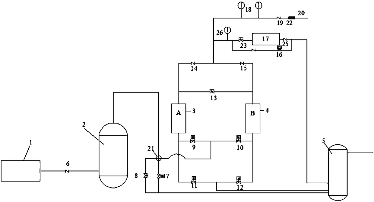
[0030] A purging and purification system inside a hydrogen generator, comprising a hydrogen generator 1, a gas-water separator 2, a liquid seal 5 and a hydrogen purifier connected through pipelines, the hydrogen generator 1 is connected to the Gas-water separator 2 is connected, and described hydrogen purifier comprises purifier A cylinder 3 and purifier B cylinder 4, and the bottom of purifier A cylinder 3 is provided with solenoid valve 2 9, and the bottom of purifier B cylinder 4 is provided with solenoid valve Three 10, solenoid valve two 9 and solenoid valve three 10 are connected in series to form circuit one, and the lower part of purifier A cylinder 3 and purifier B cylinder 4 is also provided with circuit two in parallel with circuit one, and solenoid valve four 11 and Solenoid valve five 12.

[0031] The upper part of the purifier A cylinder 3 and the purifier B cylinder 4 is connected through a pipeline and is provided with a pressure regulating valve 6 13, the puri...

Embodiment 2

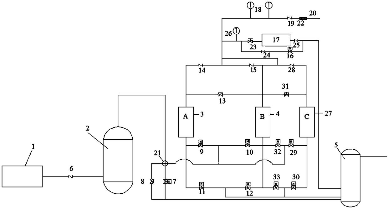
[0042] A purging and purification system inside a hydrogen generator, comprising a hydrogen generator 1, a gas-water separator 2, a liquid seal 5 and a hydrogen purifier connected through pipelines, the hydrogen generator 1 is connected to the The gas-water separator 2 is connected, and the hydrogen purifier includes a purifier A cylinder 3, a purifier B cylinder 4, and a purifier C cylinder 27. The lower part of each purifier cylinder is provided with a circuit 1 through the pipeline. On the circuit 1, a solenoid valve 2 9 and a solenoid valve 3 10 are arranged between the purifier A cylinder 3 and the purifier B cylinder 4. On the circuit 1, the purifier B cylinder 4 Electromagnetic valve seventeen 32 and electromagnetic valve fourteen 29 are also arranged between the remaining purifier C cylinders 27. The lower part of purifier A cylinder 3, purifier B cylinder 4, purifier C cylinder 27 is also provided with circuit 2 in parallel with circuit 1, and circuit 2 is provided wi...


PUM


Abstract

The invention discloses a purging and purifying system inside a hydrogen generator. The purging and purifying system comprises the hydrogen generator, a gas-water separator, a liquid seal and a hydrogen purifier which are connected through pipelines. The hydrogen generator is connected with the gas-water separator through a first one-way valve, and the gas-water separator is connected with the liquid seal through a multi-way connector. The hydrogen purifier comprises at least two sets of purifier cylinders, and the lower portions of all the purifier cylinders are connected through pipelines toform a first loop. Two sets of solenoid valves are arranged on the positions, between every two adjacent sets of purifier cylinders, of the first loop, and the lower portions of all the purifier cylinders are further connected with the first loop in parallel to be provided with a second loop. Solenoid valves with the same number as those of the first loop are arranged on the second loop, and theupper portions of every two adjacent sets of purifier cylinders are further connected with pressure adjusting valves. The upper portions of all the purifier cylinders are connected with outlet pipelines correspondingly, and the multi-way connector is further connected between every two adjacent sets of solenoid valves of the first loop through pipelines. The liquid seal is connected between everytwo adjacent sets of solenoid valves of the second loop through pipelines.

Description

technical field [0001] The invention relates to a hydrogen generator, in particular to a purging and purification system inside the hydrogen generator. Background technique [0002] Traditional large-scale hydrogen generators usually use external inert gas to discharge internal residual gas, and then separate the inert gas into hydrogen, which not only increases the tedious process of external gas source, but also increases the separation device of inert gas, making the whole process complicated and unnecessary. It is beneficial to safe production and increases risk factors. This new technology does not need an external gas source, and the internal gas is evacuated through the self-generated gas source, which greatly simplifies the process and operation steps, improves the safety of operation, and reduces the production input cost. [0003] As the most efficient and clean energy source, hydrogen has become a research hotspot in various countries. Hydrogen production by elec...

Claims


Application Information

Patent Timeline
Patent Type & Authority Applications(China)
IPC IPC(8): C25B9/00C25B15/08C25B1/04
CPCC25B1/04C25B9/00C25B15/08Y02E60/36
Inventor 苏峰王寿荣丁孝涛李家喜于平栗心镇黄方段正鹏刘丽丽
Owner SHANDONG SAIKESAISI HYDROGEN ENERGY
Learn More