Diagonal bracing and pulling device used for supporting of cast-in-place concrete wall formwork

A concrete wall and formwork support technology, which is applied to the preparation of building components on site, pillars, buildings, etc., can solve the problem of poor stability and reliability of the connection between the upper connector and the horizontal back corrugated, and can not guarantee the support strength and Stability, cumbersome adjustment of the length of the diagonal tie rods, etc., to achieve the effects of reducing construction safety hazards, convenient connection and operation, and good support strength

Pending Publication Date: 2018-08-14
魏志光
View PDF0 Cites 3 Cited by
  • Summary
  • Abstract
  • Description
  • Claims
  • Application Information

AI Technical Summary

Problems solved by technology

The problems existing in this oblique support device are: 1. Before construction, the pre-embedded position of the U-shaped steel ring needs to be determined and pre-embedded. Finally, it is necessary to remove the protruding part of the U-shaped steel ring; 2. The length adjustment of the diagonal stay is cumbersome, involving many components, and at the same time, the support strength and stability cannot be well guaranteed; 3. The upper connecting piece and the horizontal The stability and reliability of the back flute connection are poor, and the connection operation is relatively complicated

Method used


Image

  • Diagonal bracing and pulling device used for supporting of cast-in-place concrete wall formwork

Examples


Embodiment Construction

[0011] The specific embodiment of the present invention will be described with reference to the accompanying drawings.

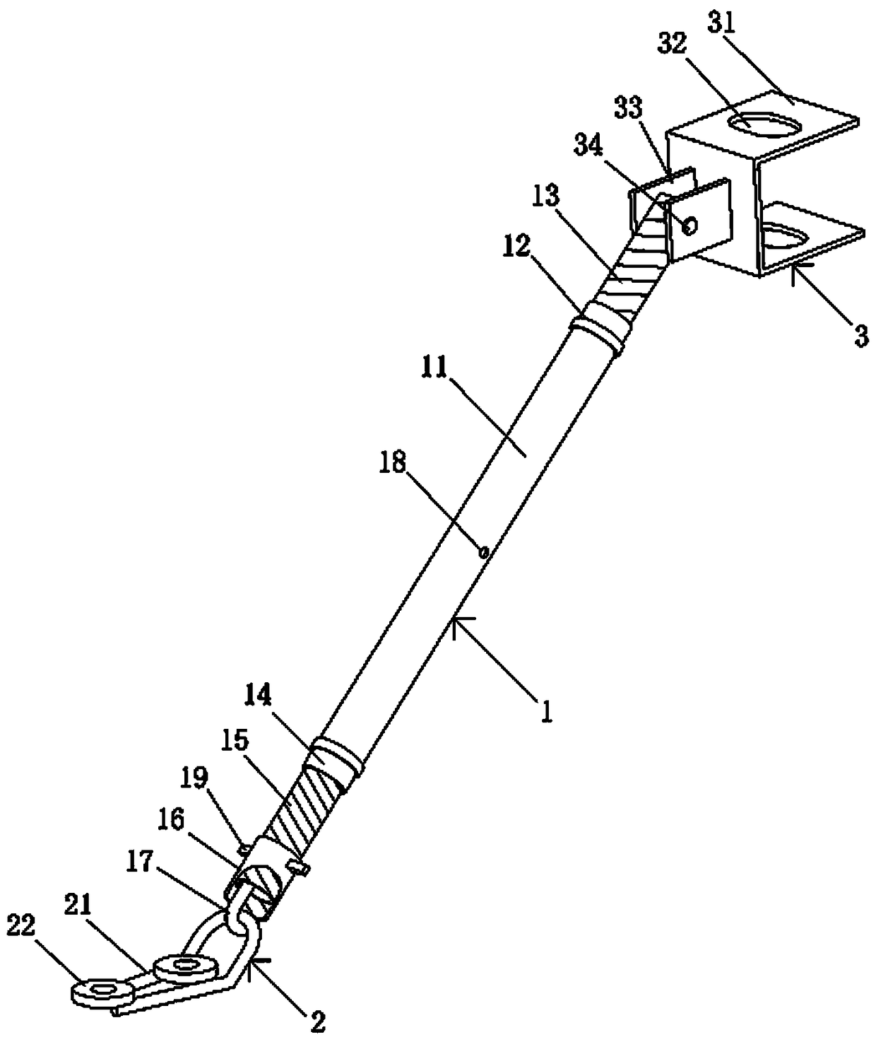
[0012] Such as figure 1 , the diagonal bracing device used for the support of cast-in-place concrete wall formwork, consists of a diagonal brace rod 1 with adjustable length, a lower fixing part 2 connected to the lower end of the diagonal brace rod 1 and a brace connected to the upper end of the diagonal brace rod 1 The upper connection part 3 is formed. The diagonal bracing rod 1 has a middle rod body 11, and the middle rod body 11 is a hollow circular rod. The upper end of the middle rod body 11 is coaxially connected with an upper nut 12 , the upper nut 12 is assembled with an upper lead screw 13 , and the upper end of the upper lead screw 13 is hingedly connected with the upper connecting piece 3 . The lower end of the middle rod body 11 is coaxially connected with a lower nut 14 , the lower nut 14 is assembled with a lower lead screw 15 , and the low...


PUM


Abstract

A diagonal bracing and pulling device used for supporting of a cast-in-place concrete wall formwork is composed of a diagonal bracing and pulling rod, a lower fixing piece and an upper connecting piece. The diagonal bracing and pulling rod is provided with a middle rod body, the upper end of the middle rod body is connected with an upper nut, and an upper lead screw is assembled on the upper nut and connected with the upper connecting piece in a hinged mode; and the lower end of the middle rod body is connected with a lower nut, a lower lead screw is assembled on the lower nut and provided with a pulling hook, and a fastening nut is assembled at the lower lead screw. The lower fixing piece is provided with a U-shaped connecting ring with the forward arc-shaped end, the front portion of theU-shaped connecting ring upwarps by 45 degrees, the pulling hook is hung at the arc-shaped end of the U-shaped connecting ring in a hooked mode, and anchor bolt gaskets are arranged on the rear portion of the U-shaped connecting ring; the upper connecting piece is provided with a transverse back arris connecting piece, through pin holes are formed in two wing plates of the transverse back arris connecting piece, and lug plates are arranged on the outer side of a web plate of the transverse back arris connecting piece; and the upper lead screw is connected with the upper connecting piece through a pin shaft in a hinged mode. The diagonal bracing pulling device is simple in structure and convenient to use, and the safe and reliable performance of supporting and connecting is good.

Description

technical field [0001] The invention relates to cast-in-place concrete wall formwork support in building construction, in particular to a diagonal bracing device for cast-in-place concrete wall formwork support. Background technique [0002] In the cast-in-place concrete wall formwork support system, inclined support rods and oblique stays are usually set up, and the verticality of the wall formwork is corrected through the combination of pull and top, and at the same time, the support strength and formwork of the wall formwork are improved during the concrete pouring process. The stability of the support system. The method in which the above-mentioned inclined support rods and oblique stays are arranged separately has the problems of complex structure, inconvenient assembly and operation, high construction cost and low efficiency. The prior art discloses a diagonal tie rod used in conjunction with a pre-embedded U-shaped steel ring to correct and support the verticality of...

Claims


Application Information

Patent Timeline
Patent Type & Authority Applications(China)
IPC IPC(8): E04G25/06
CPCE04G25/06
Inventor 魏志光
Owner 魏志光
Why Eureka
Try Eureka