
Automated Valve Mechanism for Dewatering Integrated Equipment

A technology for washing water and equipment, applied in the field of automatic valve mechanism, can solve the problems of inability to control and close in time, affecting the working environment, heavy and laborious rotation, etc., and achieves the effect of low production cost, convenient and fast operation, and avoidance of opening and closing work.

Active Publication Date: 2019-01-22
JIANGSU CHENLONG VALVE MFG CO LTD
View PDF7 Cites 0 Cited by
  • Summary
  • Abstract
  • Description
  • Claims
  • Application Information

AI Technical Summary

Problems solved by technology

The valves used in the fluid control system range from the simplest cut-off valve to the various valves used in the extremely complex automatic control system. Due to the high friction of the meshing transmission, the manual control valve device will consume more power, and the operator needs to use a large force to control the valve switch. The rotation is relatively heavy and laborious, and it will also emit a large noise. As a result, the working environment is affected. In addition, the manually controlled valve cannot be closed in time, which will lead to excessive waste of water flow.

Method used


Image

  • Automated Valve Mechanism for Dewatering Integrated Equipment
  • Automated Valve Mechanism for Dewatering Integrated Equipment
  • Automated Valve Mechanism for Dewatering Integrated Equipment

Examples


Embodiment Construction

[0017] The present invention will be further described below in conjunction with accompanying drawing:

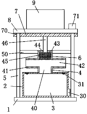
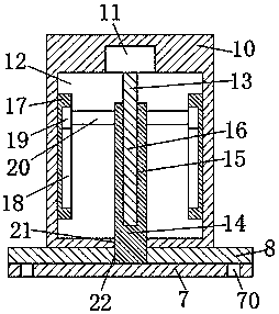
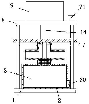
[0018] Such as Figure 1-Figure 3 As shown, an automatic valve mechanism for an integrated water-washing device of the present invention includes a fixed base 1 and an equipment water tank main body 2 fixedly installed on the fixed base 1, and the fixed base 1 is placed on the The left and right ends of the main body of the equipment water tank 2 are symmetrically provided with polished rods 5 extending upward. The top of the polished rod 5 is fixedly provided with a top support 8, and the middle of the top surface of the top support 8 is fixedly provided with a valve driving body 9. The equipment water tank A water inlet pipe 4 is installed on the top of the main body 2, and a water delivery pipe 41 extending left and right is installed on the top of the water inlet pipe 40. A valve cover 43 is installed on the top of the water delivery pipe 41, and a water delivery hole 4...


PUM


Abstract

The invention discloses an automatic valve mechanism for a washing and dehydrating integrated device. The automatic valve mechanism for the washing and dehydrating integrated device comprises a fixedbase and a device water tank main body which is fixedly installed on the fixed base, upwards extending polished rods are symmetrically arranged at the left end and the right end of the device water tank main body on the fixed base, a top support is fixedly arranged at the top of the polished rods, a valve driving main body is fixedly arranged in the middle of the top end surface of the top support, the top of the device water tank body is provided with a water inlet pipe, and the top of the water inlet pipe is provided with a water conveying pipe extending leftwards and rightwards, a valve cover is installed at the top of the water conveying pipe, and a water conveying hole with the left portion communicating with the right portion is arranged in the water conveying pipe. According to theautomatic valve mechanism for the washing and dehydrating integrated device, structure is simple, design is safe and reasonable, water delivery of the device water tank body can be automatically controlled, and the opening and closing work of manually operating the valve is avoided; operation is convenient and quickly, the matching and separation of a plug and a water inlet hole can be realized sothat the water conveying work in the device water tank main body can be timely controlled; and production cost is low, maintenance is convenient, and the device is suitable for popularization and use.

Description

technical field [0001] The invention relates to the technical field of valve equipment, in particular to an automatic valve mechanism for integrated equipment for washing and washing water. Background technique [0002] Valves are pipeline accessories used to open and close pipelines, control flow direction, adjust and control the parameters (temperature, pressure and flow) of the conveying medium. According to its function, it can be divided into shut-off valve, check valve, regulating valve and so on. The valve is a control component in the fluid delivery system, which has functions such as cut-off, adjustment, flow diversion, reverse flow prevention, pressure stabilization, flow diversion or overflow pressure relief. The valves used in the fluid control system range from the simplest cut-off valve to the various valves used in the extremely complex automatic control system. Due to the high friction of the meshing transmission, the manual control valve device will consum...

Claims


Application Information

Patent Timeline
Patent Type & Authority Patents(China)
IPC IPC(8): F16K3/24F16K31/04F16K3/316F16K31/50
CPCF16K3/246F16K3/316F16K31/047F16K31/50
Inventor 陈锦灿
Owner JIANGSU CHENLONG VALVE MFG CO LTD
Learn More