Symmetrical microwave coupling structure

A technology of coupling structure and symmetry, applied in the direction of waveguide, waveguide-type devices, circuits, etc., can solve the problems of limited use, complex modeling and calculation, etc., and achieve the effect of improving the efficiency of modeling and optimization calculation

Inactive Publication Date: 2018-08-14
成都锐烽特科技有限公司
View PDF2 Cites 0 Cited by
  • Summary
  • Abstract
  • Description
  • Claims
  • Application Information

AI Technical Summary

Problems solved by technology

Complex microwave coupling structures are limited in use due to complex modeling calculations

Method used


Image

  • Symmetrical microwave coupling structure
  • Symmetrical microwave coupling structure
  • Symmetrical microwave coupling structure

Examples


Embodiment 1

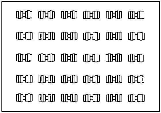
[0028] Such as figure 1 Shown.

[0029] A symmetrical microwave coupling structure connects two spaces along the Z axis. The microwave channel is composed of a branch. The branch line is composed of 9 through holes 31 connected in the Y direction.

[0030] The maximum length t of the microwave channel is less than 0.2 times the wavelength in the free space corresponding to the central operating frequency of the microwave channel.

[0031] The cross-sectional shape of the microwave channel is an "H" shape rotated 90 degrees around the Z axis.

[0032] Along the Y direction, the maximum width of each through hole 31 sequentially increases, increases, decreases, decreases, increases, increases, decreases, and decreases.

[0033] All the through holes 31 and all the branches are cylindrical bodies with the axis in the Z direction and their lengths in the Z direction are the same; all the through holes 31 and all the branches perpendicular to the Z axis The ends are flush.

Embodiment 2

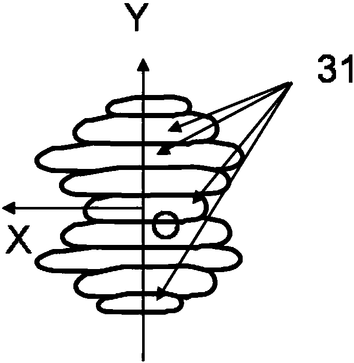
[0035] Such as figure 2 Shown.

[0036] Compared with the first embodiment, the difference of this embodiment is only: the branch is composed of 7 through holes 31 connected in the Y direction; along the Y direction, the maximum width of each through hole 31 increases, decreases, and decreases sequentially. , Increase, increase, and decrease to form a "8" shape. The cross-sectional shape of all the through holes 31 is rectangular. The rectangular through holes 31 are connected in the Y direction through their adjacent sides.

Embodiment 3

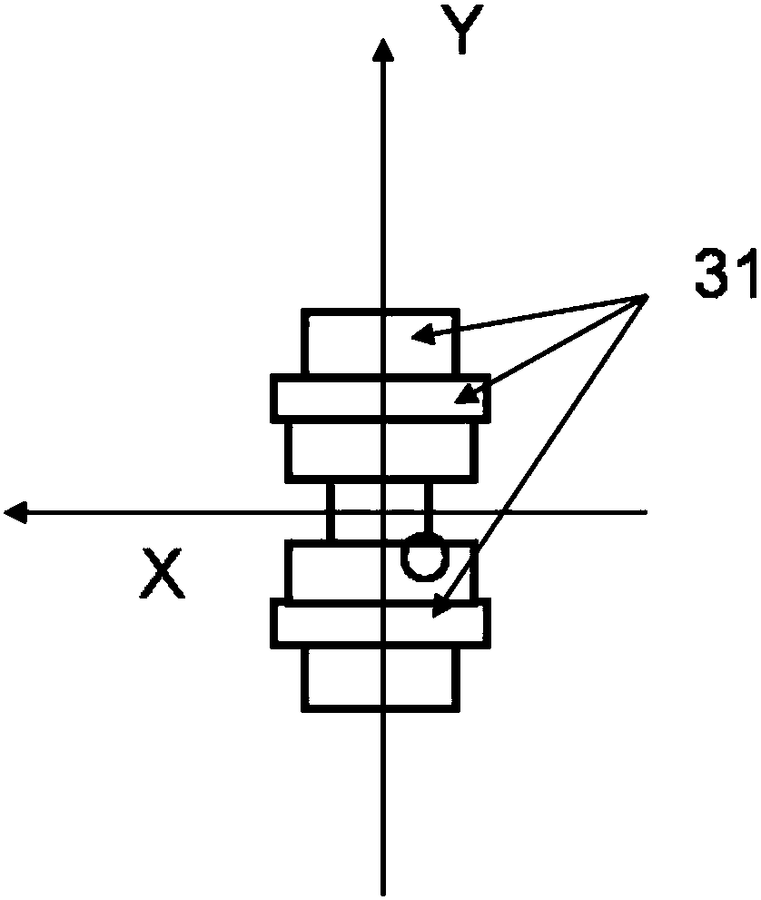
[0038] Such as image 3 Shown.

[0039] Compared with Embodiment 2, the difference of this embodiment is only that the microwave channel is rotated 90 degrees around the Z axis.


PUM


Abstract

The invention discloses a symmetrical microwave coupling structure adopting a microwave channel composed of a plurality of rectangular through holes or through holes in other shapes communicating withone another to be matched with various microwave circuits or communicate various microwave areas. The microwave channel is bilaterally symmetrical. Compared with the existing similar scheme, the symmetrical microwave coupling structure can be significantly improved in modeling optimization computing efficiency. The microwave circuit is smaller in volume and wider in work bandwidth. Particularly,the symmetrical microwave coupling structure can be matched with different transmission lines, comprising coaxial lines, rectangular waveguides, circular waveguides, ridged rectangular waveguides or circular waveguides, SIM (substrate integrated waveguide), micro strips and strip lines, within the frequency range of ultra wide band, can also be used for being matched with the transmission lines perpendicular to and reversed with the axis, and can further be used for being matched with various transmission lines which twist for different angles around the axis. The symmetrical microwave coupling structure is mainly applied to communication and radar systems in various microwave, millimeter wave and terahertz wave bands.

Description

Technical field [0001] The present invention relates to a microwave component, in particular, to a compact matching coupling structure for broadband matching of various transmission lines with other microwave structures, and a microwave coupling structure for effectively connecting two spaces. Background technique [0002] In various microwave systems, the matching problem of transmission lines is common. This is because the main function of all microwave transmission lines is to transfer as much microwave energy as possible to the target device. In order to achieve this goal, various matching circuits and mode converters are required according to the input impedance and operating mode of the target device. [0003] The existing matching circuits and mode converters have complex structures, large volumes, and narrow bandwidths, especially in coaxial and waveguide circuits. [0004] On the other hand, microwave coupling structures connecting two spaces are common. The shape of the ...

Claims


Application Information

Patent Timeline
Patent Type & Authority Applications(China)
IPC IPC(8): H01P3/12
CPCH01P3/12
Inventor 王清源
Owner 成都锐烽特科技有限公司
Why Eureka
Try Eureka