An equipment station with fire extinguishing function

A technology of equipment stations and functions, applied in the direction of fire rescue, etc., can solve problems such as property safety impacts, and achieve an easy-to-achieve effect

Inactive Publication Date: 2019-04-16
徐州致诚会计服务有限公司
View PDF6 Cites 0 Cited by
  • Summary
  • Abstract
  • Description
  • Claims
  • Application Information

AI Technical Summary

Problems solved by technology

[0004] In view of the above-mentioned automatic monitoring sub-station for air quality, when the automatic air quality monitoring sub-station encounters a fire, due to the manual inspection system, it is generally impossible to ensure that the personnel are in place at the first time, so that the air quality will inevitably be affected. The property safety of the automatic monitoring substation has a serious impact. The invention provides an equipment station with a fire extinguishing function. This equipment station can extinguish the fire of the equipment inside it, and has the advantages of low cost of use and easy guarantee of fire extinguishing reliability. specialty

Method used


Image

  • An equipment station with fire extinguishing function
  • An equipment station with fire extinguishing function
  • An equipment station with fire extinguishing function

Examples


Embodiment 1

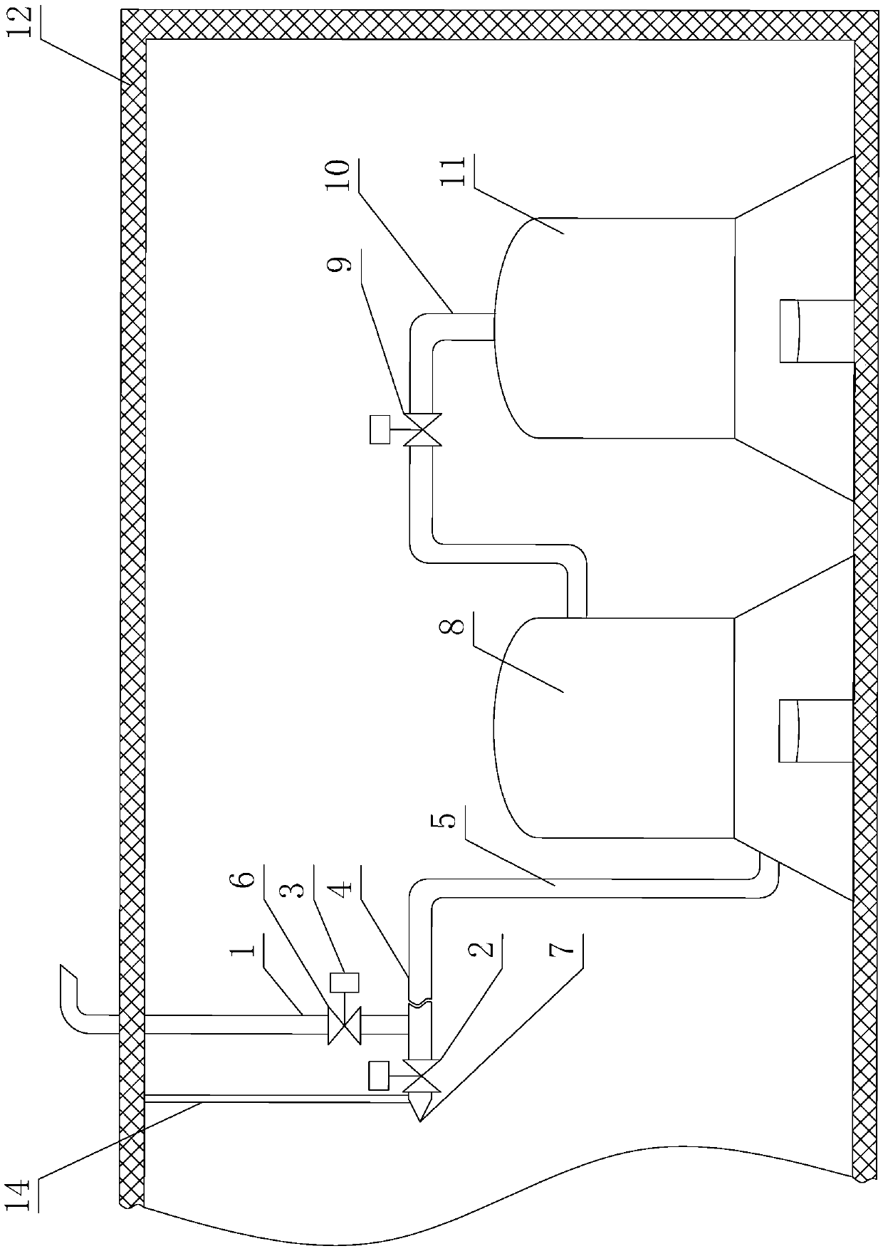
[0039] Such as Figure 1 to Figure 3 As shown, an equipment station with a fire extinguishing function includes a factory building 12 and a dry powder output system installed in the factory building 12. It is characterized in that the dry powder output system includes an air source device 11, a dry powder container 8, an air source pipe 10 and output pipe 5;

[0040] The air source pipe 10 is used as a communication pipe between the air source device 11 and the dry powder container 8, and the first shut-off valve 9 is connected in series on the air source pipe 10;

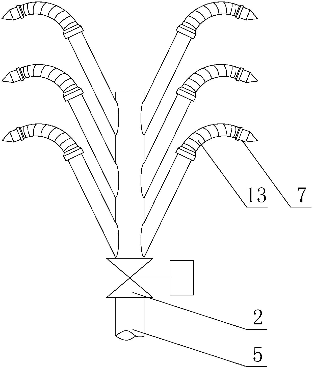
[0041] One end of the outlet pipe 5 is connected to the dry powder container 8, and the other end of the outlet pipe 5 is provided with a nozzle 7;

[0042] It also includes a third cut-off valve 2 connected in series on the output pipe 5;

[0043] Both the first cut-off valve 9 and the third cut-off valve 2 are connected with a drive mechanism 3 for driving each to change the on-off state, and the drive mechanis...

Embodiment 2

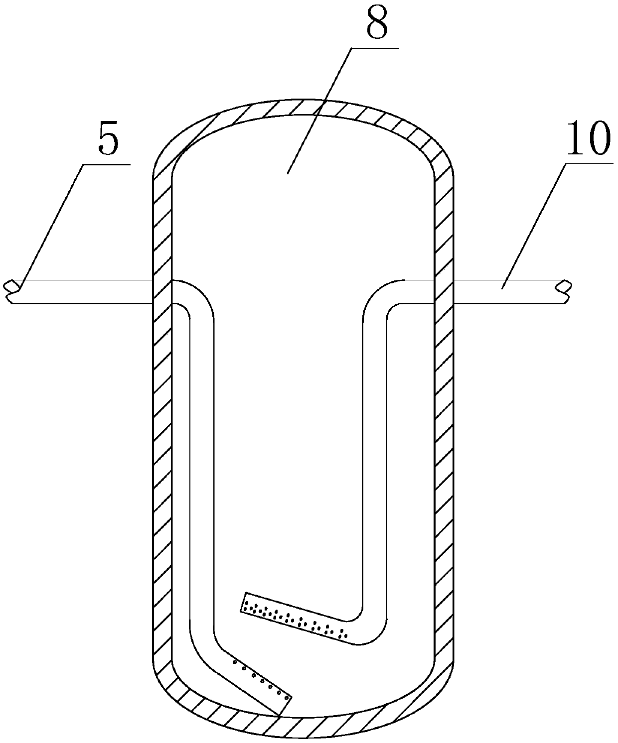
[0048] Such as Figure 1 to Figure 3 As shown, this embodiment is further limited on the basis of Embodiment 1: as the specific outlet form of the gas source pipe 10 and the inlet form of the output pipe 5, the uniform ends of the gas source pipe 10 and the output pipe 5 extend to the dry powder container 8 , and both the air source pipe 10 and the output pipe 5 extend to the pipe section in the dry powder container 8, which is a cantilever pipe section;

[0049] The outlet end of the gas source pipe 10 is located above the inlet end of the output pipe 5, and the outlet end of the gas source pipe 10 and the inlet end of the output pipe 5 are all located at the bottom of the dry powder container 8;

[0050] Both the outlet end of the gas source pipe 10 and the inlet end of the output pipe 5 are provided with a sealing plate;

[0051] The outlet pipe holes of the air source pipe 10 are a plurality of holes provided on the wall of the air source pipe 10 , and the inlet pipe hole...


PUM


Abstract

The invention discloses an equipment station with a fire extinguishing function. The station comprises plants and a dry powder output system. The dry powder output system comprises an air source device, a dry powder container, an air source pipe and an output pipe, wherein a first cut-off valve is further connected to the air source pipe in series; one end of the output pipe is connected with thedry powder container, and nozzles are arranged at the other end of the output pipe; the dry powder output system further comprises a third cut-off valve connected to the output pipe in series; the first cut-off valve and the third cut-off valve are correspondingly connected with driving mechanisms, wherein the driving mechanism is an electric mechanism or a pneumatic mechanism; the nozzles are multiple, and all the nozzles are connected with the output pipe through a section of flexible pipe; and the dry powder output system further comprises fixing devices, wherein the number of the fixing devices is equal to the number of the nozzles, each fixing device is provided with a mounting station used for mounting a nozzle, and each mounting station is provided with a nozzle. The equipment station can extinguish fire in the equipment station, and meanwhile has the characteristics that using cost is low, and the fire extinguishing reliability is easy to guarantee.

Description

technical field [0001] The invention relates to the technical field of fire fighting equipment, in particular to an equipment station with a fire extinguishing function. Background technique [0002] In the existing technology, with the development of communication technology and the increasing abundance of smart devices, many outdoor unattended workstations have appeared in the existing technology, such as monitoring stations for geological disaster monitoring in mountainous areas, and various process nodes in sewage treatment systems. Data collection stations, many air quality monitoring stations set up in urban areas, etc. The work of the above monitoring stations is closely related to people's production, life and health. With the deteriorating environment and ecology, people are more and more concerned about the living environment. Therefore, the normal work of the above monitoring stations and collection stations is very important. [0003] Taking the air quality moni...

Claims


Application Information

Patent Timeline
Patent Type & Authority Patents(China)
IPC IPC(8): A62C3/16A62C31/02A62C37/50
CPCA62C3/16A62C31/02A62C37/50
Inventor 杨佳志
Owner 徐州致诚会计服务有限公司
Why Eureka
Try Eureka