Symmetrical antenna in layer construction method

a layer construction and antenna technology, applied in the field of antenna arrays, can solve the problems of insufficient removal of disadvantages caused by asymmetrical excitation, radiation loss in response to patch coupling, and interference, and achieve the effect of improving radiation characteristics

Inactive Publication Date: 2005-05-19
ROBERT BOSCH GMBH
View PDF10 Cites 18 Cited by
  • Summary
  • Abstract
  • Description
  • Claims
  • Application Information

AI Technical Summary

Benefits of technology

[0010] According to still another exemplary embodiment of the antenna array according to the present invention, the two signal feeds are a parallel system of two printed or etched lines, and in the layer construction, two symmetrically arranged dipole halves are provided in a subdivision (into smaller chambers), which are conductingly connected with one feed line each. In a layer construction, etched or printed lines are simple and well suited feedings. The common subdivision of the symmetrically situated dipole halves spatially limits the radiation and thereby improves the radiation characteristics.
[0011] According to another exemplary embodiment, the signal lines are buried in a di-electrical layer of the layer construction, so that the signal lines do not run along the surface, but in a l...

Problems solved by technology

In asymmetrical excitation, what may be particularly disadvantageous is the susceptibility to failure by spurious radiation from outside, which corrupts the signal.
An additional disadvantage of asymmetrical excitation is radiation losses in response to a patch coupling because of the required field vector rotation ...

Method used


Image

  • Symmetrical antenna in layer construction method
  • Symmetrical antenna in layer construction method
  • Symmetrical antenna in layer construction method

Examples


Embodiment Construction

[0032] In the figures, the same reference numbers designate the same or functionally equivalent components. All the drawings are schematic, and, for the purpose of increased clarity of the topology of each respective layer configuration, the illustrations are not to scale.

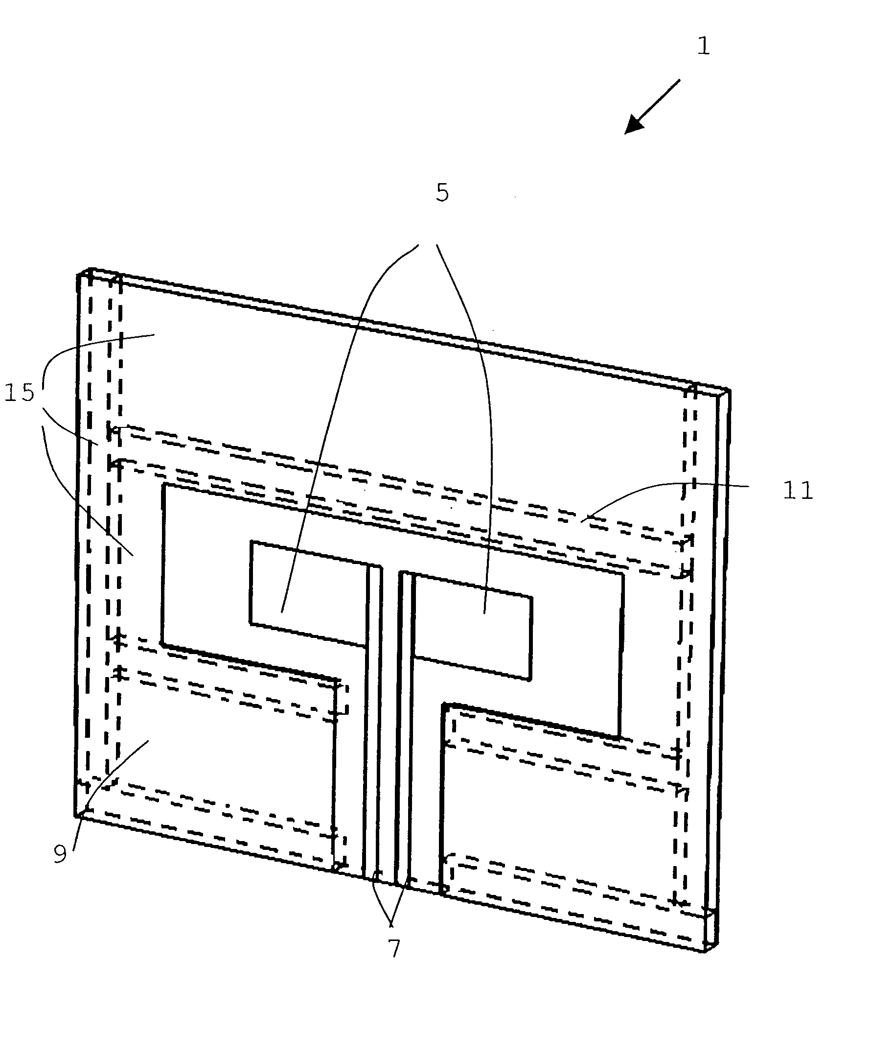
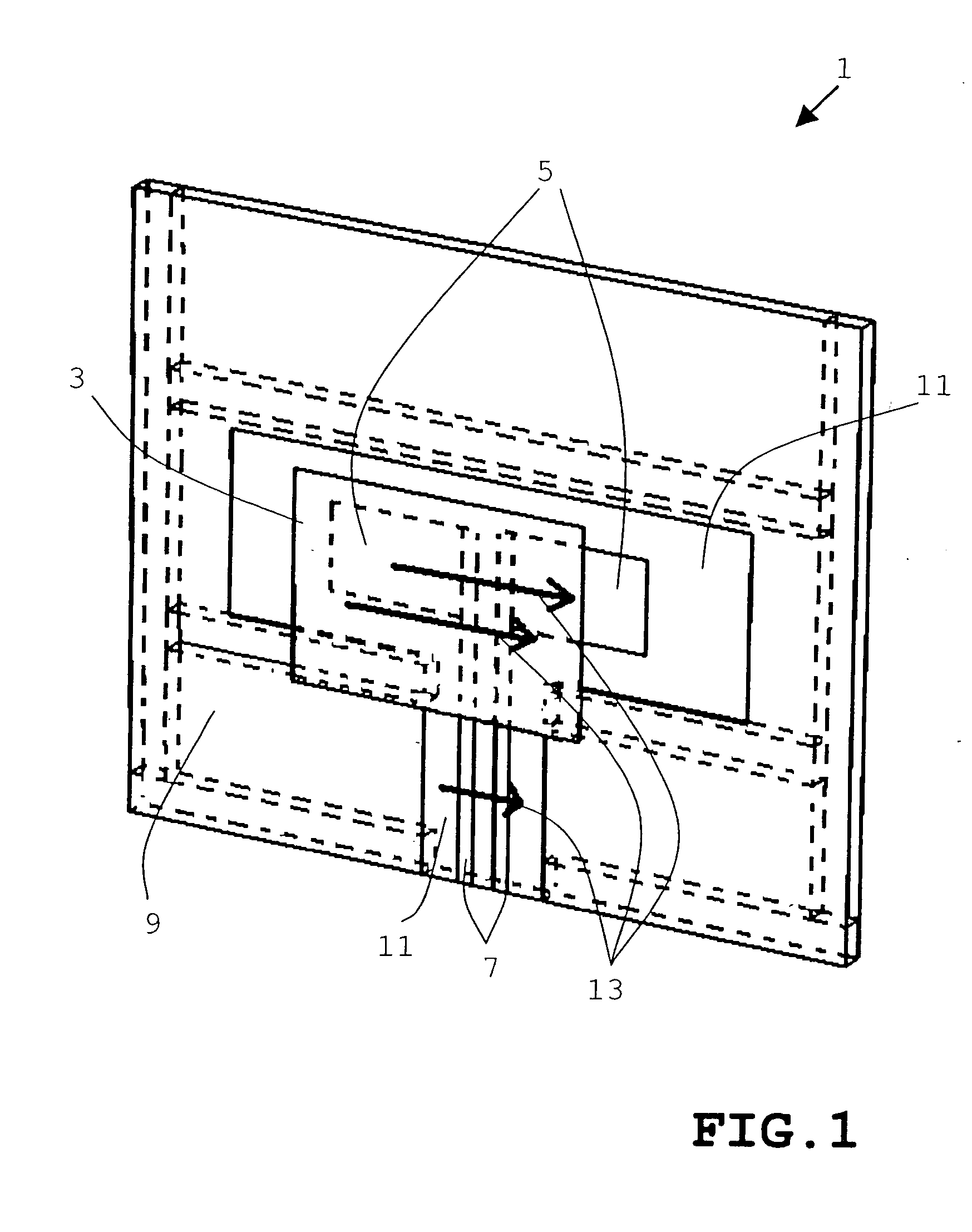
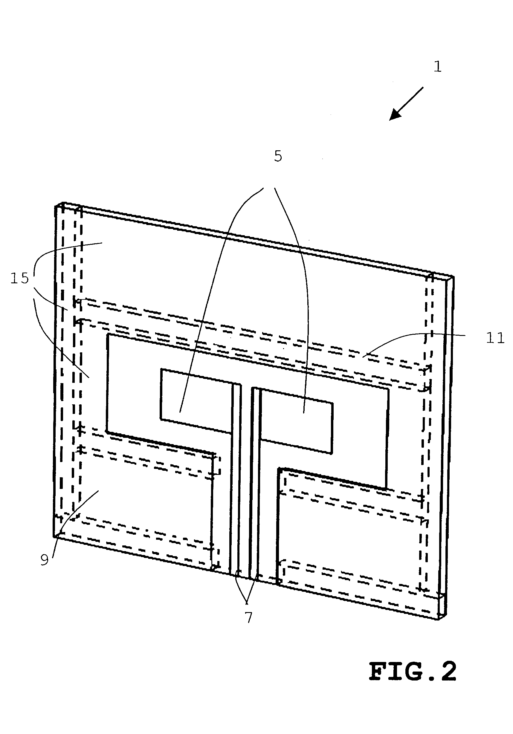
[0033]FIG. 1 shows a schematic view of an example of antenna array 1 according to the present invention, having a representation of field vectors 13 of the electrical fields. Patch 3, a rectangular sheet metal platelet, is situated parallel to the stratification of antenna array 1, at a distance of approximately the 0.1-fold of the wavelength of the transmitted radiation via flat dipole 5 on the stratification system, that is about 1.2 mm, at 24 GHz.

[0034] The distance is not limited to this measure, but rather, it may vary. A range of from 0.01 to 0.2 of the wavelength is very suitable. The transmitted radiation has a frequency in a range about 26 GHz. Because of the dielectric load and coupling with dipole 5, p...


PUM


Abstract

An antenna array, especially for spacing ascertainment or speed ascertainment in the surroundings of motor vehicles, includes devices for transmitting and/or receiving signal waves, which includes a shielding layer construction, made up of at least two layers, which includes the transmitting or receiving devices at least in part. To achieve above all a good immunity to interference, the antenna array includes a differential input buried in a dielectric layer and it includes a transmitting and/or receiving dipole, which is composed of two separate dipole halves.

Description

FIELD OF THE INVENTION [0001] The present invention relates to an antenna array and especially to an antenna array made by a layer construction method for ascertaining vehicle spacing or speed in the surroundings of motor vehicles. BACKGROUND INFORMATION [0002] There are systems in which the distance and the speeds are measured by radar (microwaves), especially short-range radar. In this context, above all, small antenna arrays in compact layer building method are used. In the antenna arrays in this field having microstrip feeding, coplanar feeding or slot coupling, asymmetrical excitation is always or generally involved. In asymmetrical excitation, the signal lines (feed lines and return lines) are not developed in the same way, as in symmetrical excitation, but rather, the signal is on the feed line and the “return line” is at ground, and is usually developed as a metallic plane. In asymmetrical excitation, what may be particularly disadvantageous is the susceptibility to failure ...

Claims


Application Information

Patent Timeline
IPC IPC(8): G01S7/03G01S13/93H01Q1/32H01Q1/38H01Q1/48H01Q1/52H01Q9/04H01Q9/06H01Q9/16H01Q9/28H01Q21/08
CPCH01Q1/48H01Q1/52H01Q21/08H01Q9/285H01Q9/065
Inventor VOIGTLAENDER, KLAUS
Owner ROBERT BOSCH GMBH
Why Eureka
Try Eureka