Supercharge Your Innovation With Domain-Expert AI Agents!

A glass feeding rack for a weekly polishing machine

A technology for weekly polishing machine glass and glass, which is applied in the direction of grinding workpiece supports, grinding machine parts, grinding/polishing equipment, etc., which can solve the problems of low processing efficiency, low yield, and inconvenient loading and unloading.

Inactive Publication Date: 2019-12-27
深圳市天航光学设备有限公司
View PDF5 Cites 0 Cited by
  • Summary
  • Abstract
  • Description
  • Claims
  • Application Information

AI Technical Summary

Problems solved by technology

[0003] At present, the weekly polishing machines on the market are mainly divided into two types. One is the manual method. Each periphery is polished in turn. After each side is polished, it needs to be manually switched to the other side for polishing. The processing efficiency is low, and the four rounded corners Poor polishing effect of parts and special-shaped glass
The other is the automatic rotary polishing method. The glass is fixed in the middle of the machine, and the glass is clamped up and down. The glass is continuously rotated 360 degrees, and the brush moves back and forth accordingly to realize the polishing of the entire periphery in one clamping. This method is efficient High, but the yield rate is low, and it is inconvenient to load and unload the material. When loading the material, the glass needs to be installed in the jig frame, and then put into the machine and clamped, and the jig frame needs to be taken out. When the fixture frame is put in, the glass is easy to shift and chip during the process of clamping and removing the fixture frame, which requires high technical skills for the operator, and the glass clamped in this way is easy to shift during the polishing process

Method used


Image

  • A glass feeding rack for a weekly polishing machine
  • A glass feeding rack for a weekly polishing machine
  • A glass feeding rack for a weekly polishing machine

Examples


Embodiment Construction

[0017] The present invention will be further described below in conjunction with the accompanying drawings.

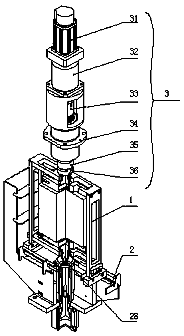
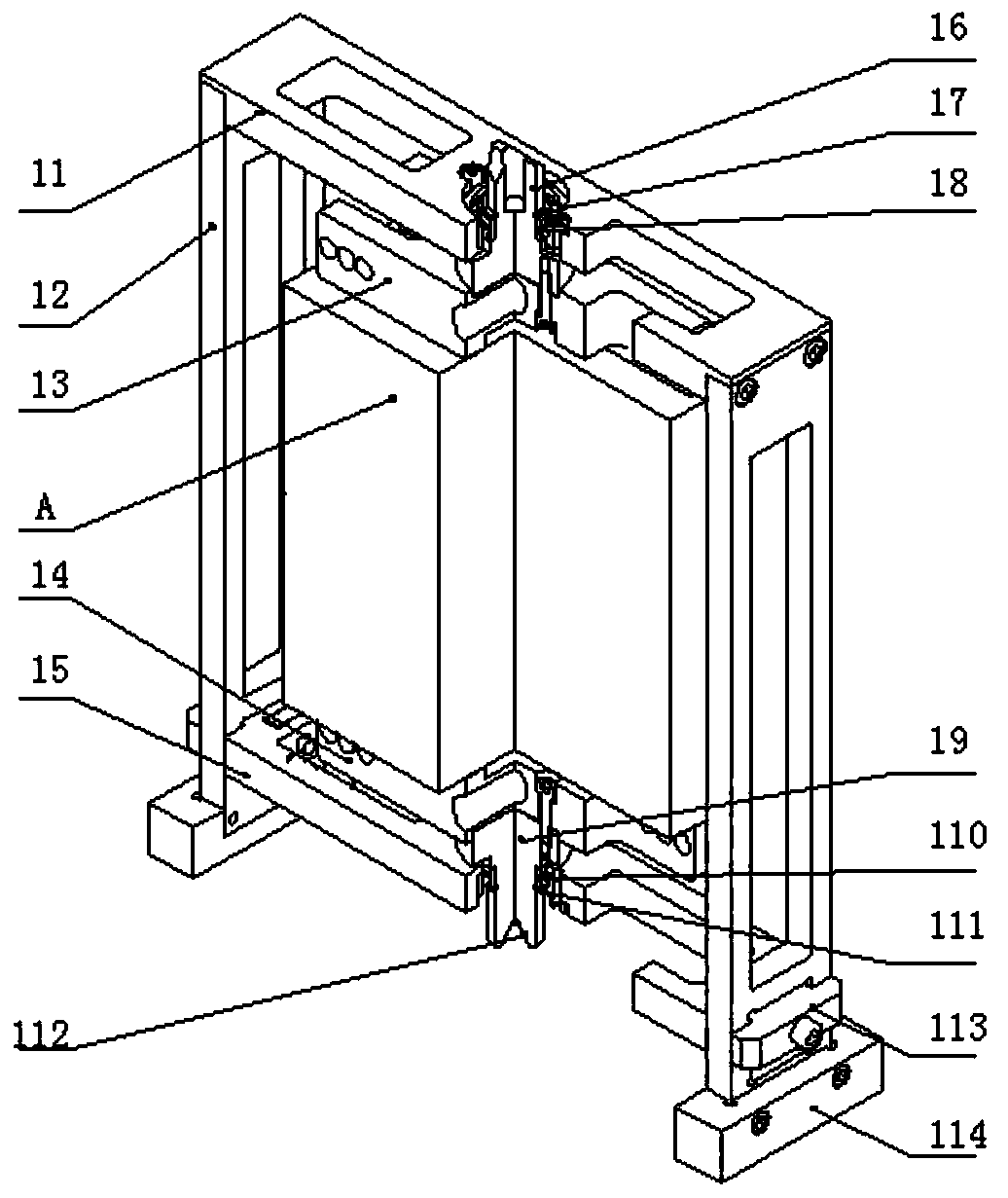
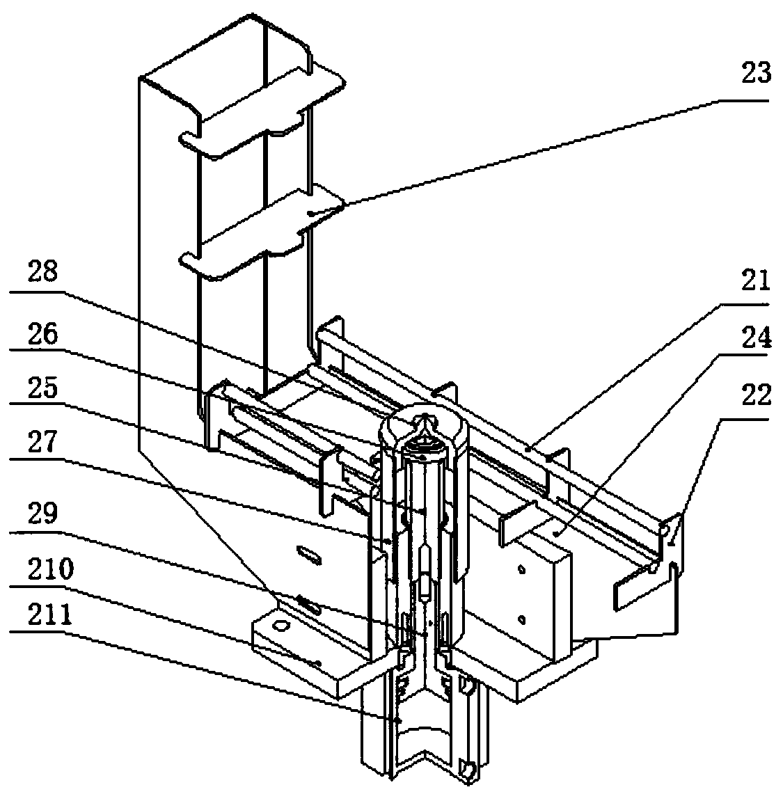
[0018] see as figure 1 -- image 3 As shown, this specific embodiment includes a glass feeding rack 1, a feeding rail mechanism 2 and a rotating mechanism 3; the glass feeding rack 1 includes an upper fixing plate 11, a side fixing plate 12, an upper pressing plate 13, a lower pressing plate 14, Lower fixing plate 15, upper rotating chuck 16, shaft circlip 1 17, deep groove ball bearing 1 18, lower rotating top 19, deep groove ball bearing 2 110, shaft circlip 2 111, taper hole structure 112 , clamping block 113 and guide slider 114; both sides between the upper fixing plate 11 and the lower fixing plate 12 are provided with side fixing plates 12; the inner side of the upper fixing plate 11 is provided with an upper pressing plate 13; The inner side of the lower fixing plate 15 is provided with a lower pressure plate 14; the outer side of the bottom of the side fixin...


PUM


Abstract

The invention relates to a novel glass feeding frame of a circumference polishing machine and a rotary structure thereof, and belongs to the technical field of glass polishing. A lower rotary tip is arranged in the middle of a lower pressing plate of a lower fixed plate; a deep groove ball bearing II and an external circlip II are arranged on the outer wall of the lower rotary tip; a tapered holestructure is formed at the bottom of the lower rotary tip; a guide rod support plate is arranged on one end of guide rods of a feeding guide rail mechanism; a plurality of front limiting blocks are arranged on the other ends of the guide rods; guide sliding blocks are matched with guide rail grooves between a plurality of guide rods; a lifting shaft is arranged on one side of the guide rail grooves; and a deep groove ball bearing III is arranged on the top of the lifting shaft. The novel glass feeding frame has the advantages of high feeding and discharging speed, convenience and reliability in clamping glass, the polishing of the whole circumference can be completed only by clamping once, while the glass rotates without shifting, the one-time clamping height (yield) is increased, and twoprocesses of the circumference and hole polishing can be completed by clamping once, so that secondary clamping is avoided, the clamping time is saved, and the yield is increased.

Description

technical field [0001] The invention relates to a glass feeding rack for a peripheral polishing machine, which belongs to the technical field of glass polishing. Background technique [0002] With the improvement of the processing technology of the mobile phone lens industry and market demand, the four (or more, including rounded corners) sides (periphery) of the lens also need to be polished, and corresponding equipment is required. This type of equipment is called a weekly polishing machine ( Or edge sweeping machine, edge throwing machine, edge grinding machine). [0003] At present, the weekly polishing machines on the market are mainly divided into two types. One is the manual method. Each periphery is polished in turn. After each side is polished, it needs to be manually switched to the other side for polishing. The processing efficiency is low, and the four rounded corners The polishing effect of the place and special-shaped glass is poor. The other is the automatic...

Claims


Application Information

Patent Timeline
Patent Type & Authority Patents(China)
IPC IPC(8): B24B41/00B24B9/08B24B41/06B24B5/48B24B47/06
CPCB24B5/48B24B9/08B24B41/005B24B41/062B24B47/06
Inventor 雷修权
Owner 深圳市天航光学设备有限公司
Features
  • R&D
  • Intellectual Property
  • Life Sciences
  • Materials
  • Tech Scout
  • Unparalleled Data Quality
  • Higher Quality Content
  • 60% Fewer Hallucinations
Learn More