Continuous anti-pilling machine and anti-pilling production process

A shaker and shaker room technology, which is used in the filtration of dispersed particles, the separation of dispersed particles, and the removal of smoke and dust, can solve the problems of enlarging the distance and inconvenient operation of the staff, so as to increase the path, improve the kneading effect, and improve the requirements. come effect

Pending Publication Date: 2018-08-17
郭锐坤
View PDF15 Cites 0 Cited by
  • Summary
  • Abstract
  • Description
  • Claims
  • Application Information

AI Technical Summary

Problems solved by technology

[0004] However, the above-mentioned air-flow type shaker relies on the pipeline arranged outside the cabinet and communicated with the fabric channels on both sides to form a cycle to complete the process of circulating the shaker. One end of the cloth is fed into one of the Venturi tubes, and the peripheral pipe expands the distance between the staff and the entrance when loading the cloth, making it inconvenient for the staff to operate

Method used


Image

  • Continuous anti-pilling machine and anti-pilling production process
  • Continuous anti-pilling machine and anti-pilling production process
  • Continuous anti-pilling machine and anti-pilling production process

Examples


Embodiment 1

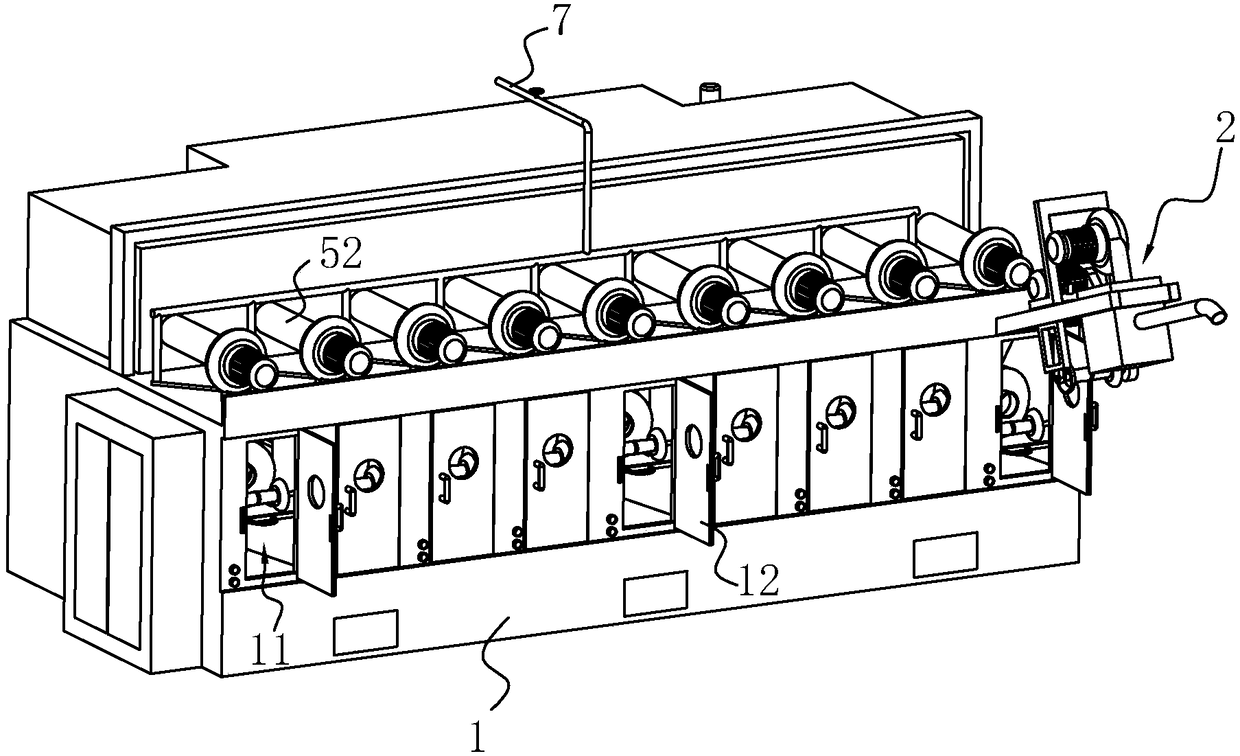
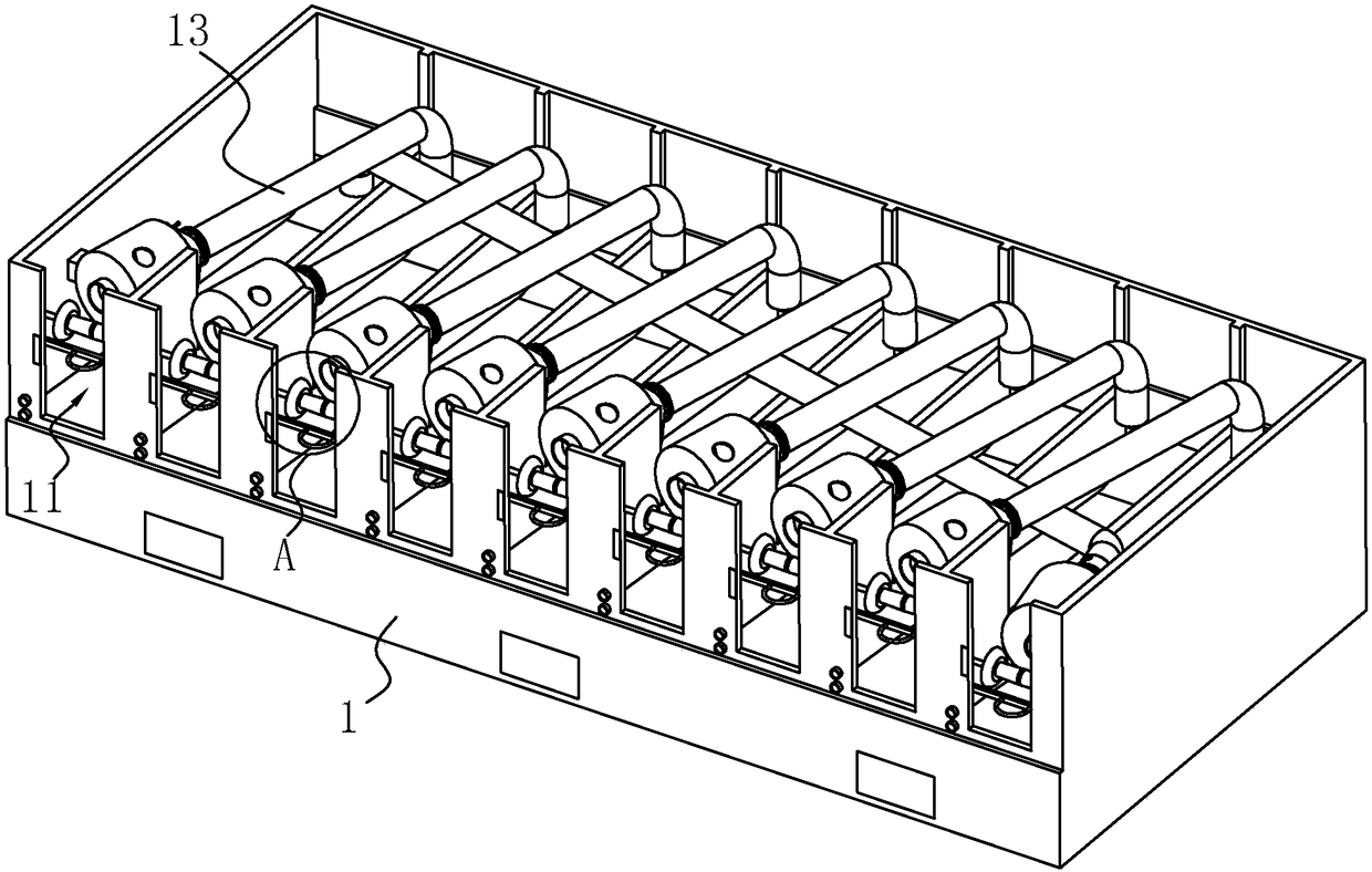
[0051] A continuous shaker, refer to figure 1 , including a case 1, in which there are N interconnected shaker chambers 11, and each shaker chamber 11 is correspondingly provided with an electromagnetic door 12, and the staff can send the fabric through the shaker chamber 11 after opening the electromagnetic door 12 middle. In addition, a cloth outlet device 2 is provided outside the Nth grain chamber 11, so as to facilitate sending the finished fabric out of the grain chamber 11.

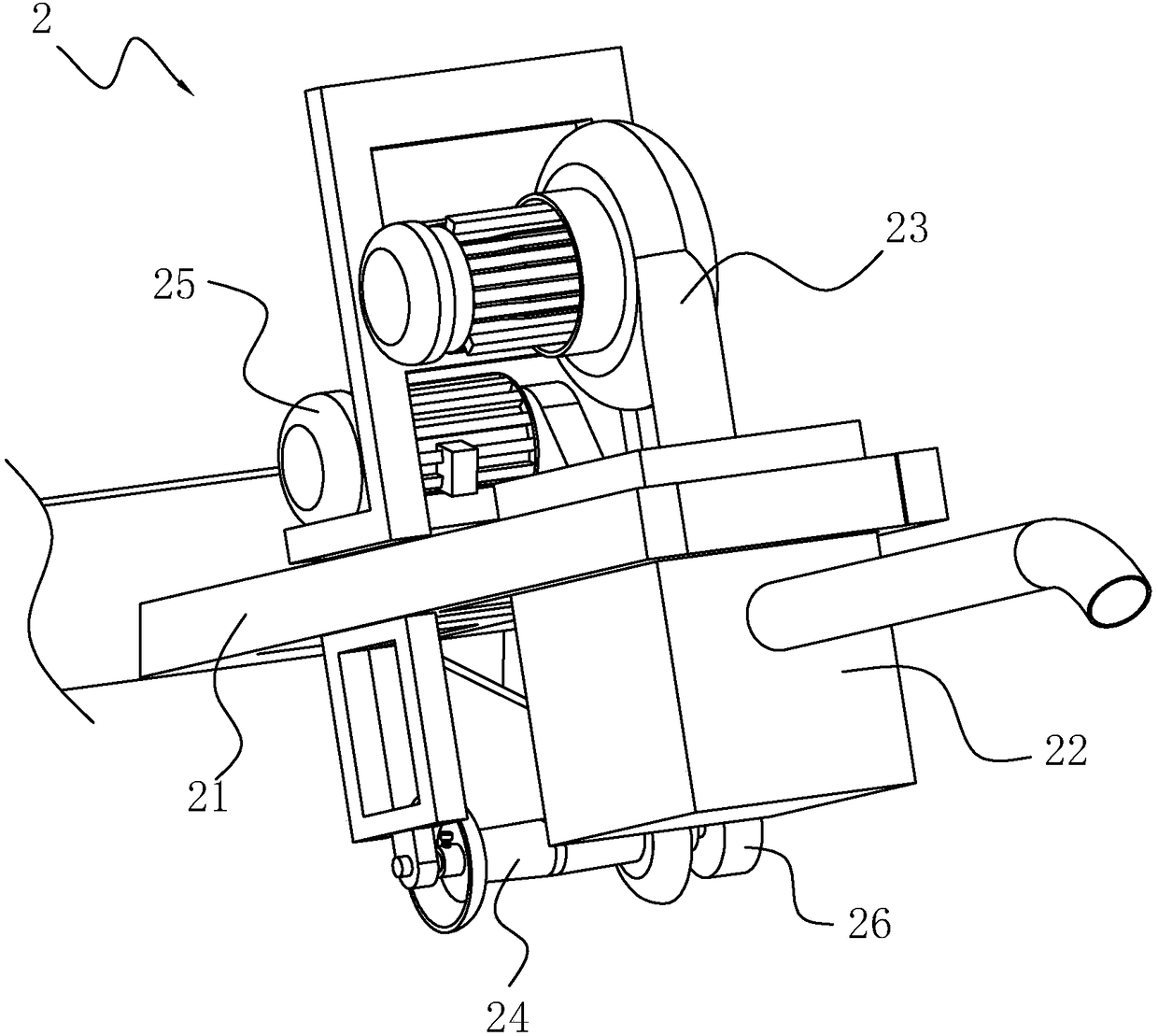
[0052] refer to figure 2 The cloth outlet device 2 includes a bracket 21 which is fixedly connected to the chassis 1 and is inclined upwardly. The lower surface of the bracket 21 is fixedly connected with a cloth outlet venturi tube 22. Out of cloth fan 23. A cloth outlet roller 24 is provided at the entrance of the cloth outlet venturi pipe 22 , and the cloth outlet roller 24 is rotatably connected to the bracket 21 . Moreover, the upper surface of the support 21 is also provided with a cloth...

Embodiment 2

[0063] A production process for eccentric pellets, based on the continuous eccentric pellet machine described in Embodiment 1, comprising the following steps:

[0064] S1: cloth feeding; all cloth lifting rollers 31 and cloth lifting fans 4 start to work, the heating device 51 does not work, and the staff feeds the fabric from the entrance of the first venturi tube 13 until the fabric passes through the Nth venturi tube 13 outlets are sent out, and then, the end of the fabric is tied, and the fabric will circulate in N Venturi tubes 13;

[0065] S2: Dust removal; all cloth lifting rollers 31 and cloth lifting fans 4 stop working, and after 10 seconds, the dust exhaust fan starts to discharge the dust and lint generated in the filter area 55 and the cloth feeding process to the collector through the action of the dust removal fan 62 inside bag 63;

[0066] S3: Shake particles; the dust exhaust fan stops working, and at the same time, the heating device 51 and the cloth lifting...


PUM


Abstract

The invention discloses a continuous anti-pilling machine and an anti-pilling production process, relating to the technical field of fabric finishing machinery. The anti-pilling machine comprises a casing, wherein the casing is internally provided with N inter-communicated anti-pilling chambers and N venturi tubes; the inlets of the venturi tubes are respectively located in different anti-pillingchambers, and the outlets of the venturi tubes are located in the anti-pilling chambers adjacent to the inlets; the Nth venturi tube crosses the interior of the casing, so that the outlet thereof is located in the first anti-pilling chamber; the inlet of each venturi tube is provided with a cloth lifting device, and each anti-pilling chamber is provided with a door at the inlet of the corresponding venturi tube; by the fact that all the venturi tubes are placed within the casing, the inlet and the outlet of each venturi tube are located in two adjacent anti-pilling chambers, and the outlet ofthe last venturi tube is located in the first anti-pilling chamber, the cycle anti-pilling process of a fabric is realized, the outside occupied space of the anti-pilling machine is reduced and clothfeeding by a worker is facilitated; meanwhile, the venturi tubes are inclined, the path of the fabric in the venturi tubes is increased, and the anti-pilling effect of the fabric is improved.

Description

technical field [0001] The invention relates to the technical field of fabric post-finishing machinery, more specifically, it relates to a continuous shaker and shaker production process. Background technique [0002] In the textile industry, after the fabric has been brushed, combed and sheared, and then shaken, the fluff that is disorderly arranged on the surface of the fabric can be curled into a granular shape, and the fluff can be arranged in an orderly manner, with a plump feel and good verticality. . At present, for the technology of shaking pellets, the most commonly used one is the shaking pellet machine. [0003] For example, the Chinese utility model patent with the notification number CN201942896U discloses a kind of airflow type shaker, including a frame and a cabinet with a fabric channel arranged on the frame. The cloth guide device at the front end of the Venturi tube and the impact grille plate at the rear end of the Venturi tube. Connected with the fabri...

Claims


Application Information

Patent Timeline
IPC IPC(8): D06C11/00D06C7/00D06B1/02D06B1/00B08B15/04B01D46/02
CPCB01D46/02D06B1/00D06B1/02D06C7/00D06C11/00B08B15/04
Inventor 郭锐坤
Owner 郭锐坤
Why Eureka
Try Eureka