Sampling device with time-interleaved optical clocking

A sampling device, optical technology, applied in optics, optical components, optical analog/digital converters, etc., can solve the problems such as the hold time of analog/digital converters and the limitation of sampling rate that can no longer be reduced

Active Publication Date: 2015-01-07
ROHDE & SCHWARZ GMBH & CO KG
View PDF4 Cites 11 Cited by
  • Summary
  • Abstract
  • Description
  • Claims
  • Application Information

AI Technical Summary

Problems solved by technology

[0004] The disadvantage of this publication is that the sampling rate is limited since the necessary hold time for the A / D converter can no longer be reduced

Method used


Image

  • Sampling device with time-interleaved optical clocking
  • Sampling device with time-interleaved optical clocking
  • Sampling device with time-interleaved optical clocking

Examples


Embodiment Construction

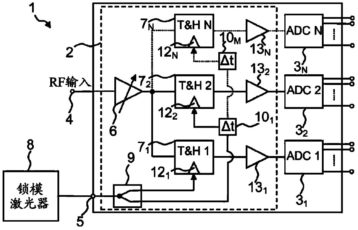
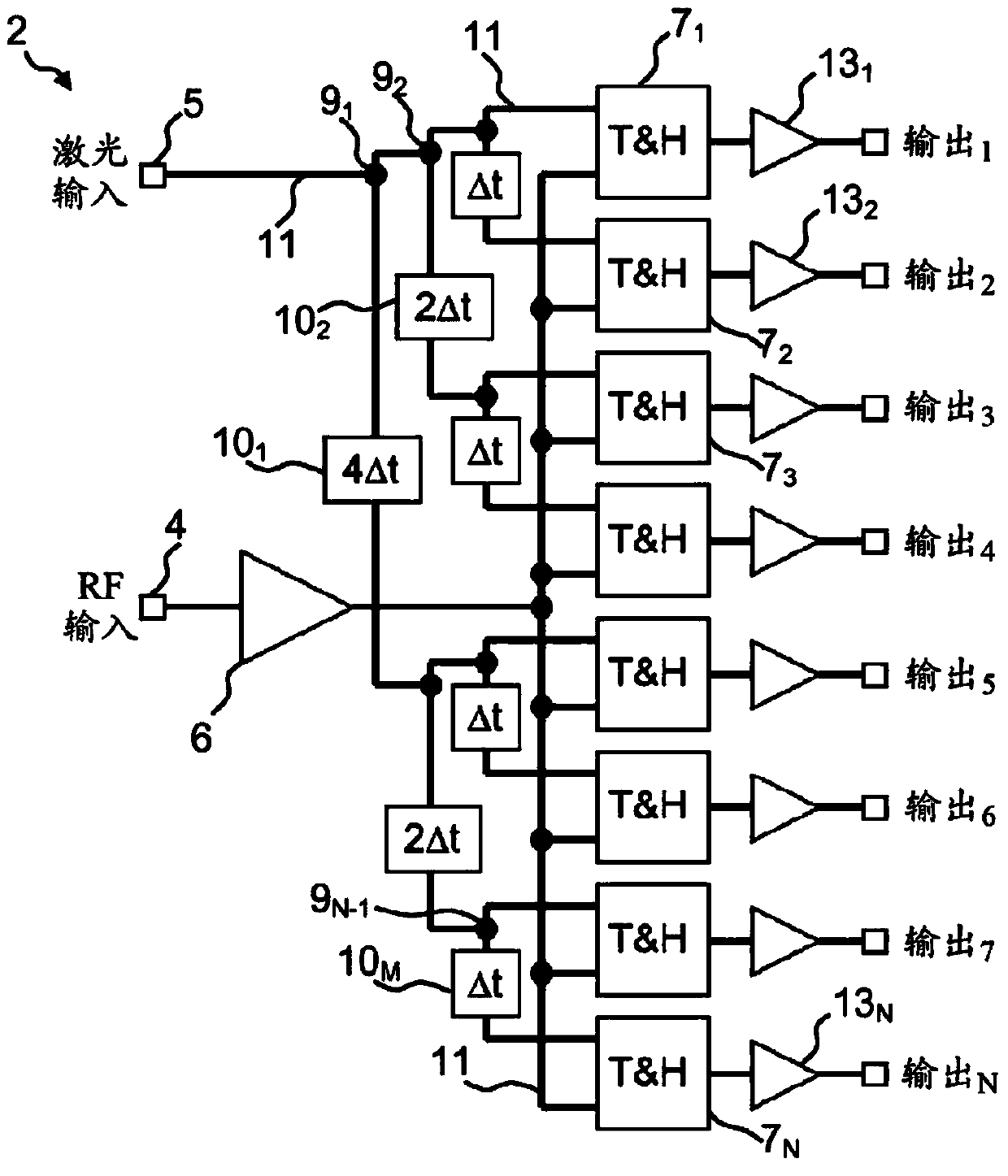
[0029] figure 1 A high speed sampling unit 1 is shown comprising a sampling arrangement 2 comprising a track and hold unit 7 operating in a time interleaved mode 1 , track and hold unit 7 2 To track and hold unit 7 N . In some cases, the high-speed sampling unit 1 can be integrated in a single chip or ASIC (Application Specific Integrated Circuit). However, it is also possible that the sampling device 2 can be integrated on its own chip, while the analog / digital converter 3 1 , A / D converter 3 2 to A / D converter 3 N on a separate chip. It should be noted that the A / D converter 3 1 , A / D converter 3 2 to A / D converter 3 N Included for better understanding only in figure 1 However, they are not essential components of the present invention. The sampling device 2 also comprises a first input port 4 and a second input port 5 . An electrical input signal, ie an RF (Radio Frequency) signal, is input to the first input port 4 . RF signals are high frequency signals with ...


PUM


Abstract

A sampling device (2) comprising a first input port (4) and a second input port (5), wherein an input-signal is fed to the first input port (4) and wherein an optical clock signal is fed to the second input port (5). The sampling device (2) comprises a plurality of track and hold units (7 1 , 7 2 , 7 N ), wherein each of the plurality of track and hold units (7 1 , 7 2 , 7 N ) is connected to the first input port (4). The plurality of the track and hold units (7 1 , 7 2 , 7 N ) is further connected to the second input port (5) through an optical waveguide (11) in such a manner that the plurality of tack and hold units (7 1 , 7 2 , 7 N ) operate in a time-interleaved mode.

Description

technical field [0001] The invention relates to a sampling device comprising a plurality of track-and-hold units operating in a time-staggered mode. Background technique [0002] The increasing need for broadband communication systems is driving an increase in the need for suitable measurement systems. To analyze those communication systems, the measurement system needs really high bandwidth and good jitter performance. In order to obtain a measurement system with such good jitter performance, the entire clock tree must be stable. [0003] The publication "Optically clocked track-and-hold for high-speed, high-resolution analog-to-digital conversion" by E.W Jacobs et al. (IEEE MWP, April 2004, pp. 190-192) describes a possible A track-and-hold unit used in an analog-to-digital converter, wherein the track-and-hold unit receives an optical clock. Therefore, the track-and-hold unit includes two photodiodes for generating a current that is fed into the diode circuit, switchin...

Claims


Application Information

Patent Timeline
Patent Type & Authority Applications(China)
IPC IPC(8): G11C27/02H03M1/12H03K3/42G02F7/00G02B6/125G11C13/04
CPCG02B6/2861H03M1/1245H03K3/42H03M1/1215G11C13/04G02B6/125G02F7/00G11C27/024G11C27/02G02B2006/12147G02B2006/1215G02B2006/12154
Inventor 奥利弗·兰多尔特
Owner ROHDE & SCHWARZ GMBH & CO KG
Why Eureka
Try Eureka