A post-standard decorative hollow body railing and its construction method

A hollow body and railing technology, which is applied to railings, buildings, building structures, etc., can solve the problems of heavy formwork construction workload, uneven arrangement of railings, and high secondary maintenance costs, etc., to reduce the difficulty of formwork installation and reinforcement , Reduce repair and maintenance costs, improve work efficiency

Active Publication Date: 2020-01-24
CHINA FIRST METALLURGICAL GROUP
View PDF6 Cites 0 Cited by
  • Summary
  • Abstract
  • Description
  • Claims
  • Application Information

AI Technical Summary

Problems solved by technology

[0005] This construction method has the following disadvantages: If the level of protection and formwork fixing workers is not high during the pouring of the hollow railings, the overall arrangement of the railings will be uneven after forming; after the railings are installed, due to the subsequent construction of the upper ring beam, the hollow railings must be decorated Encapsulation of formwork results in heavy workload and difficulty in formwork construction, and it is not easy to remove the formwork, and when pouring the upper ring beam, it is easy to cause concrete to pollute the railings, and it is not easy to clean, resulting in quality problems and rework. In addition, this splicing installation requires many construction joints, and the connection Too random, the joints are often treated with post-painting, the effect cannot be achieved, the joints are easy to crack, and the secondary maintenance cost is relatively high

Method used


Image

  • A post-standard decorative hollow body railing and its construction method
  • A post-standard decorative hollow body railing and its construction method
  • A post-standard decorative hollow body railing and its construction method

Examples


Embodiment Construction

[0032] The principles and features of the present invention are described below in conjunction with the accompanying drawings, and the examples given are only used to explain the present invention, and are not intended to limit the scope of the present invention.

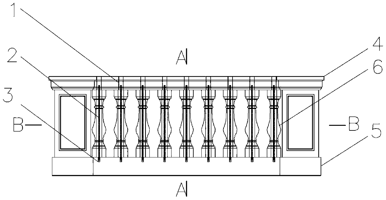
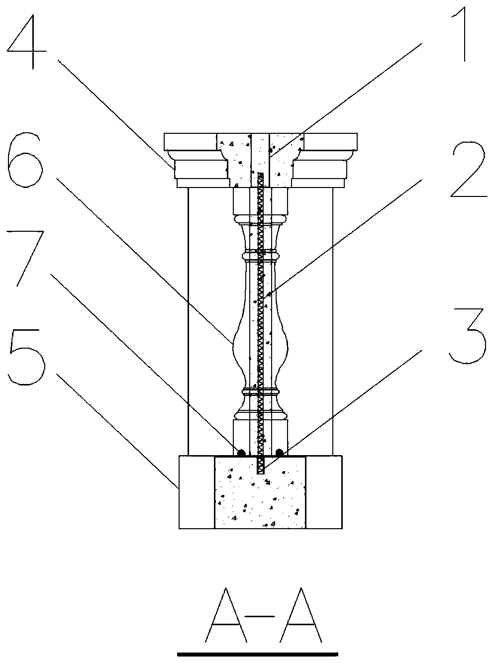
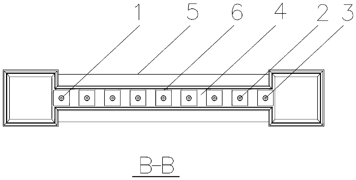
[0033] Such as figure 1 , figure 2 , image 3 As shown, a post-standard decorative hollow railing includes an upper concrete ring beam 4, a lower concrete topping 5, a hollow decorative railing 6, a rubber gasket 7 and a positioning column 2, and the hollow decorative railing 6 is arranged on the upper concrete ring beam 4 Between the upper concrete ring beam 4 and the lower concrete roof 5, there are pouring holes 1 that run through the entire upper concrete ring beam 4 at the places facing the decorative railings 6 of the hollow body, and the pouring holes 1 set on the upper concrete ring beam 4 The quantity is multiple, specifically 1, 2, 3, 4, 5, 6 or 7, etc., and all the pouring holes 1 are on the same strai...


PUM


Abstract

The invention relates to a post-made decorative hollow railing. The railing comprises an upper concrete ring beam, a lower concrete pressing top, hollow decorative railing bodies, rubber washers and positioning columns, the hollow decorative railing bodies are arranged between the upper concrete ring beam and the lower concrete pressing top, pouring holes penetrating through the entire upper concrete ring beam are formed in the positions, facing the hollow decorative railing bodies, of the upper concrete ring beam, positioning holes matched with the positioning columns are formed in the positions, facing the hollow decorative railing bodies, of the lower concrete pressing top, the rubber washers are arranged between the hollow decorative railing bodies and the lower concrete pressing top,the positioning columns are arranged in the hollow decorative railing bodies, the two ends of the positioning columns respectively extend into the pouring holes and the positioning holes, and the pouring holes and the hollow decorative railing bodies are filled with concrete. The railing has the advantages that the problems of easy damage and pollution in the installation of a traditional railingcan be reduced, and the tight connection between the hollow decorative railing bodies, the upper concrete ring beam and the lower concrete pressing top is ensured without gaps.

Description

technical field [0001] The invention relates to the technical field of building construction, in particular to a post-standard decorative hollow railing and a construction method thereof. Background technique [0002] The decorative hollow railing is a common fence structure set up on the verandas, corridors, verandahs, stairs and shed roofs of antique buildings. It has the important function of fence protection to prevent tourists from slipping and falling. [0003] At present, the conventional construction methods in the antique house construction project and some municipal garden landscapes are as follows: [0004] During construction, decorative railings are hollow and more fragile than solid railings. Therefore, traditional installation mostly adopts sequential layering, prefabricated assembly, and superimposed construction. The construction sequence is from bottom to top in-situ splicing and installation: firstly, the bottom topping concrete is poured; before the topp...

Claims


Application Information

Patent Timeline
Patent Type & Authority Patents(China)
IPC IPC(8): E04F11/18
CPCE04F11/181E04F2011/1893
Inventor 林齐鸿白冲徐琛舒刘厚胜庄佳展
Owner CHINA FIRST METALLURGICAL GROUP
Why Eureka
Try Eureka