
Power-down protection lock device

A technology of power-off protection and power-off protection, applied in the field of locks, can solve problems such as failure of electromagnetic locks, achieve simple and reliable structure, and realize the effect of real-time control

Pending Publication Date: 2018-08-17
YUANRANG IND SHANGHAI
View PDF9 Cites 2 Cited by
  • Summary
  • Abstract
  • Description
  • Claims
  • Application Information

AI Technical Summary

Problems solved by technology

However, in some occasions, there will be a power outage. During the power outage, the electromagnetic lock will fail, and the door lock is useless, which leads to some accidents.

Method used


Image

  • Power-down protection lock device
  • Power-down protection lock device
  • Power-down protection lock device

Examples


Embodiment 1

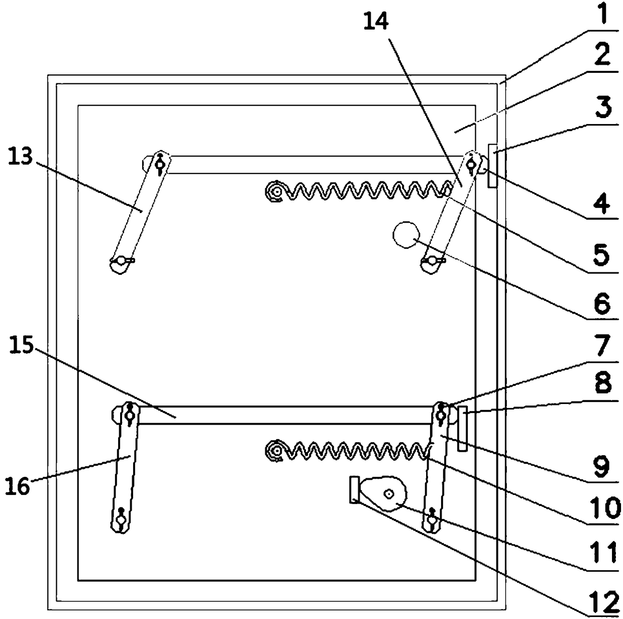
[0044] This application has designed a power-down protection lock device, such as figure 1 shown, including:

[0045] The lock body is connected to the power supply, and the door body is switched on and off according to the control signal;

[0046] Also includes:

[0047] The power-off protection mechanism is respectively connected with the power supply and the door body, and is used to lock the door body when the power is off;

[0048] The unlocking mechanism is connected with the power-off protection mechanism, and is used to drive the power-off protection mechanism to cancel the locking of the door body.

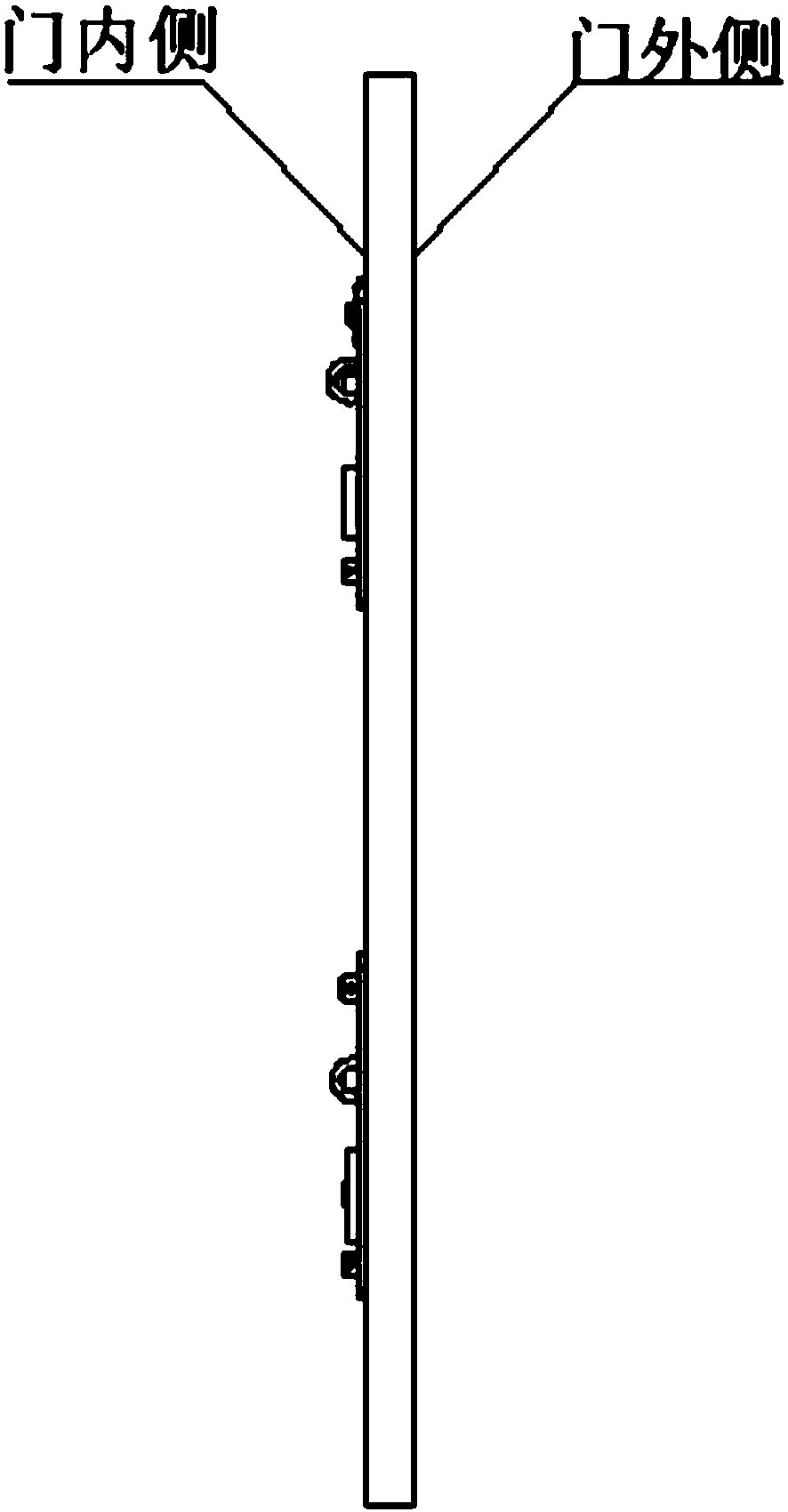
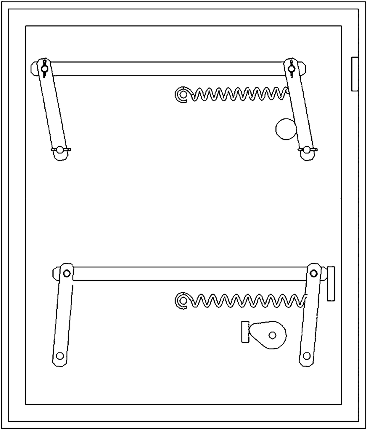
[0049] Among them such as figure 2 As shown, the lock body and the power-off protection mechanism are all arranged on the inner side of the door 2, the main body of the unlocking mechanism is arranged on the inner side of the door 2, and the key socket is arranged on the outer side of the door. By configuring the power-off protection mechanism, the door body can be a...

Embodiment 2

[0061] The similarities between this embodiment and Embodiment 1 will not be described, and only the differences will be described.

[0062] The significant difference between this embodiment and Embodiment 1 is that the connecting rod connecting the cam in this embodiment is the rotating shaft of the lock cylinder. After the key is inserted into the lock cylinder, the rotating shaft is rotated to drive the cam to rotate.

Embodiment 3

[0064] The similarities between this embodiment and Embodiment 1 will not be described, and only the differences will be described.

[0065] The significant difference between this embodiment and Embodiment 1 is that in this embodiment, the first electromagnet 1 is also arranged on the door 2, the device includes a locking mechanism, and both the first actuator and the second actuator are installed and locked. The firing pin of the mechanism and the trigger logic of the two actuators are in an OR relationship. If any actuator hits the locking mechanism, the locking mechanism will lock the door body.


PUM


Abstract

The invention relates to a power-down protection lock device. The lock device comprises a lock body, a power-down protection mechanism and an unlocking mechanism; the lock body is connected with a power supply, and a door body is opened and closed through the lock body according to a control signal; the power-down protection mechanism is correspondingly connected with the power supply and the doorbody and is used for locking the door body during outage; and the unlocking mechanism is connected with the power-down protection mechanism and is used for driving the power-down protection mechanismto withdraw locking of the door body. Compared with the prior art, the power-down protection lock device has the advantages that by configuring the power-down protection mechanism, the door body canbe automatically locked during outage, so that the technical defect that an electromagnetic lock is in an out-of-control state when the power supply is powered down is overcome, the electromagnetic lock is enabled to play a role during outage, and the electromagnetic lock can be controlled in real time; and in addition, by the arrangement of the unlocking mechanism, the locking of the power-down protection mechanism can be manually relieved, and the situation that a door cannot be opened after being automatically locked is avoided.

Description

technical field [0001] The invention relates to a lock, in particular to a power-down protection lock device. Background technique [0002] Electromagnetic locks are widely used in various industries because of their remote control characteristics. When the device protected by the lock is to be taken out or closed, the switch of the electromagnetic lock can be controlled remotely through buttons or other devices. For example, Chinese patent CN207110720U discloses a mechanical electronic lock, including: a box body; an electromagnet structure, which includes a lock core partially arranged inside the box body, a first base fixed inside the box body, and a lock cylinder set on the first base. The coil winding, the power supply for the coil winding and the switch arranged on the lock core and selectively connected in series with the coil winding by rotating the lock core; The magnetic lock bar on the second base and can selectively extend out of the box body under the action of...

Claims


Application Information

Patent Timeline
Patent Type & Authority Applications(China)
IPC IPC(8): E05B47/00
CPCE05B47/0002E05B2047/0007
Inventor 张宏宇易小雷
Owner YUANRANG IND SHANGHAI
Learn More