Multi-functional environment-friendly heat dissipating device

A cooling device and multi-functional technology, which is applied in the direction of noise reduction devices, exhaust devices, optical observation devices, etc., can solve the problems of increasing engine load and fuel consumption, increasing exhaust emissions, and increasing manufacturing costs, so as to reduce load and fuel consumption, Efforts to alleviate environmental pollution and reduce manufacturing costs

Active Publication Date: 2018-08-17
重庆恩光科技有限公司
View PDF5 Cites 2 Cited by
  • Summary
  • Abstract
  • Description
  • Claims
  • Application Information

AI Technical Summary

Problems solved by technology

[0003] In the design of traditional cooling fans, a single fan is mostly used for heat dissipation, and the thermal efficiency of the fan is not high, which often easily causes a series of adverse effects such as excessive water temperature. Moreover, the driving of the cooling fan is mostly driven by the engine, which increases the load on the engine and fuel consumption. Indirectly increase exhaust emissions and pollute the environment, while traditional rearview mirror heating devices mostly use electronic heating, which not only increases energy consumption, but also increases manufacturing costs

Method used


Image

  • Multi-functional environment-friendly heat dissipating device
  • Multi-functional environment-friendly heat dissipating device
  • Multi-functional environment-friendly heat dissipating device

Examples


Embodiment Construction

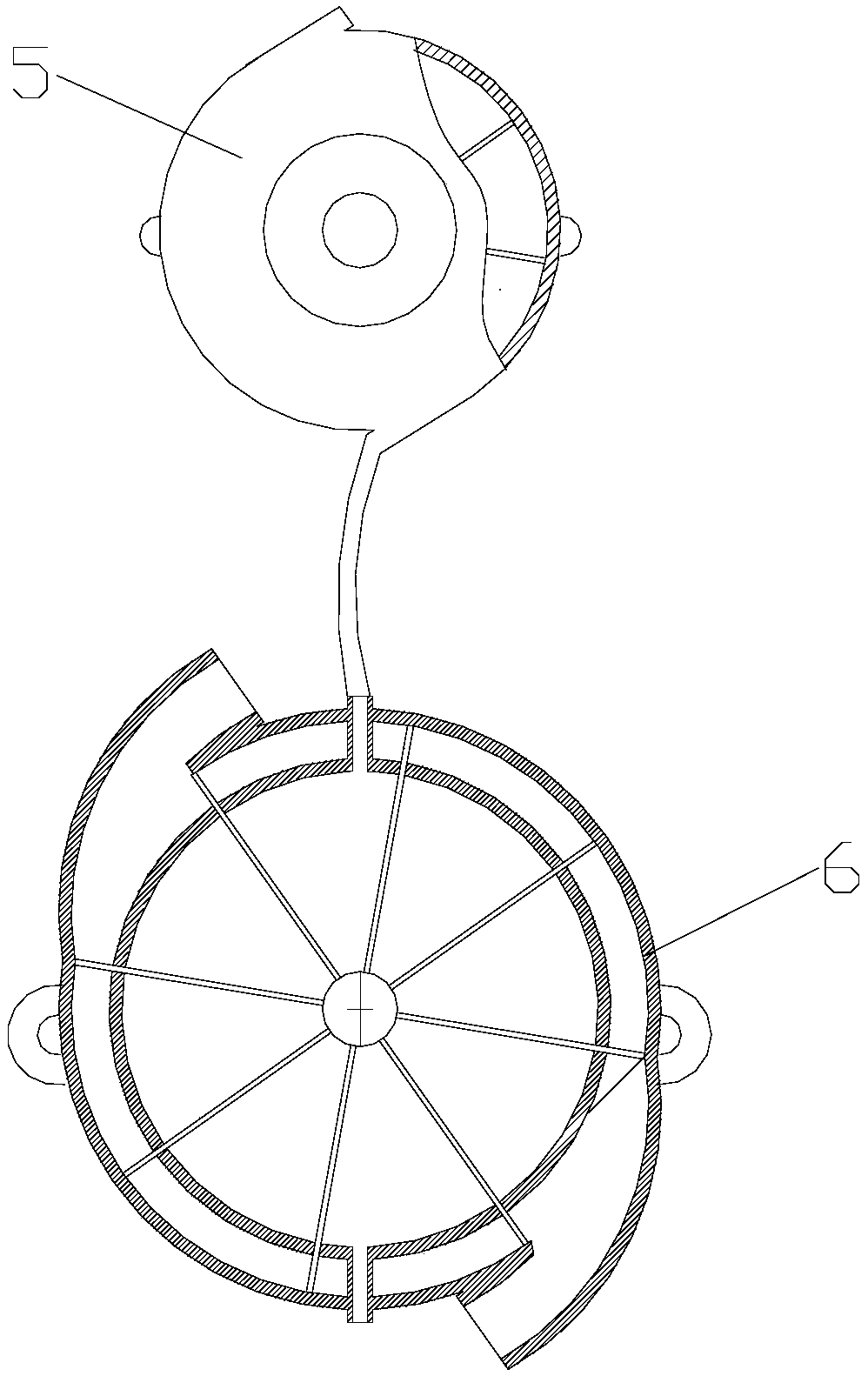
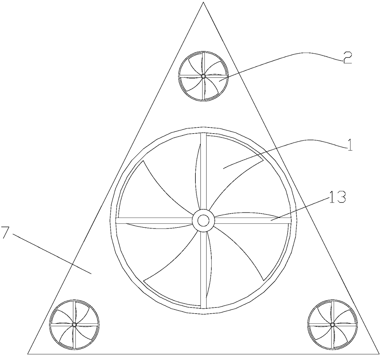
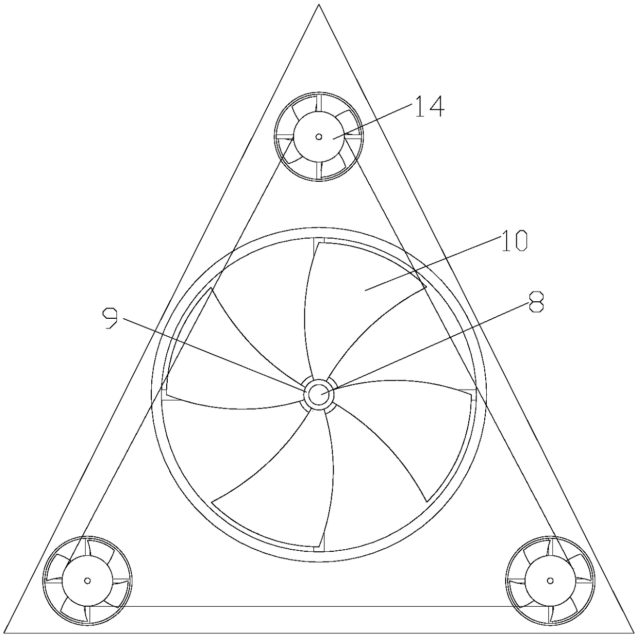
[0023] figure 1 Schematic for the structure of the present invention figure 1 It is a structural schematic diagram of the driving part I and the driving part II of the present invention, figure 2 It is the front view of the enhanced cooling fan of the present invention, image 3 It is the rear view of the enhanced cooling fan of the present invention, Figure 4 It is the front view of the triangular support plate of the present invention, Figure 5 It is a sectional view of the driving part I of the present invention, Figure 6 It is a sectional view of the driving part II of the present invention, Figure 7 It is a schematic diagram of the installation of the enhanced heat dissipation fan of the present invention, the drive part I and the drive part II, Figure 8 It is a front view and a back sectional view of the rearview mirror device of the present invention, as shown in the figure: a multifunctional environmental protection heat dissipation device of this embodiment...


PUM


Abstract

The invention discloses a multi-functional environment-friendly heat dissipating device which comprises an enhanced heat dissipating fan, a driving part I, a driving part II and a rearview mirror device, wherein the enhanced heat dissipating fan comprises a main fan head and a plurality of auxiliary fan heads; by utilization of exhaust gas, the main fan head is driven by the driving part I to rotate; a water-storage inner container is arranged inside the driving part I; the driving part II is arranged above the driving part I; by utilization of the exhaust gas, water in the water-storage innercontainer is heated to form steam, and then the auxiliary fan heads are driven by the driving part II to rotate; the steam discharged by the driving part II is utilized by the rearview mirror devicefor being heated; both the driving part I and the driving part II are fixed at the back of the enhanced heat dissipating fan; and the rearview mirror device and the driving part II are connected through a pipeline. Through the interaction among all part of the multi-functional environment-friendly heat dissipating device, not only can the heat dissipating efficiency be improved, but also the engine load and the oil consumption can be lowered, the exhaust gas emission can be reduced, and the environmental pollution can be relieved; besides, the manufacturing cost can be reduced; and a safety guarantee can be provided for a driver during the driving process on rainy days.

Description

technical field [0001] The invention relates to the field of environmental protection and energy saving, in particular to a multifunctional environmental protection cooling device. Background technique [0002] With the rapid development of the automobile manufacturing industry, the market's requirements for the functions of automobile drive components are becoming more and more diverse. At the same time, environmental protection and energy saving are advocated. How to make automobile drive components both environmentally friendly and multi-functional. [0003] In the design of traditional cooling fans, a single fan is mostly used for heat dissipation, and the thermal efficiency of the fan is not high, which often easily causes a series of adverse effects such as excessive water temperature. Moreover, the driving of the cooling fan is mostly driven by the engine, which increases the load on the engine and fuel consumption. Indirectly increase exhaust emissions and pollute th...

Claims


Application Information

Patent Timeline
IPC IPC(8): F01P5/02F01P5/04F01P5/08F01N5/02F01N5/04B60R1/06B60S1/54
CPCB60R1/0602B60S1/54F01N5/02F01N5/04F01P5/02F01P5/04F01P5/08F01P2005/025Y02T10/12
Inventor 王美琴
Owner 重庆恩光科技有限公司
Why Eureka
Try Eureka