heat sink

A heat sink and edge technology, applied in heat exchange equipment, lighting and heating equipment, laminated components, etc., can solve the problems of rising manufacturing costs, difficulty in processing louvers, and increasing surface area, so as to eliminate heat stagnation, The effect of increasing the surface area and improving the heat dissipation capacity

Active Publication Date: 2022-02-15
JAPAN
View PDF12 Cites 0 Cited by
  • Summary
  • Abstract
  • Description
  • Claims
  • Application Information

AI Technical Summary

Problems solved by technology

Therefore, there is a limit to increasing the number of peaks and valleys by reducing the distance (pitch) and increasing the surface area.
[0004] Furthermore, such a louver is difficult to process, and the louver needs to be formed before bending into continuous peaks and valleys. However, the bending process of such a louvered plate is restricted in the bending method, and the manufacturing cost also increases.

Method used


Image

  • heat sink
  • heat sink
  • heat sink

Examples


Embodiment Construction

[0048] Next, embodiments of the present invention will be described in detail based on the drawings.

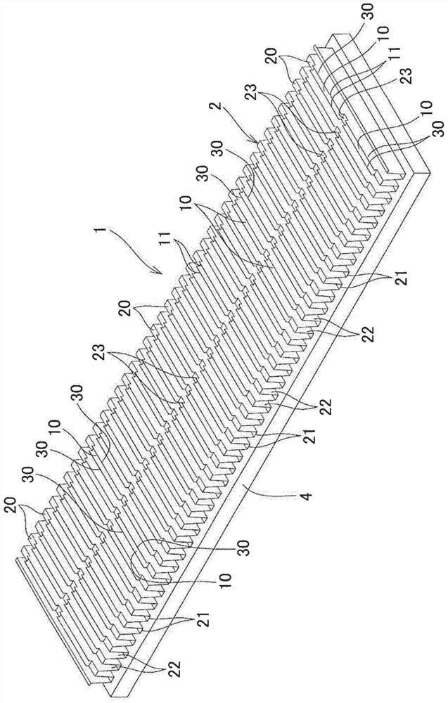
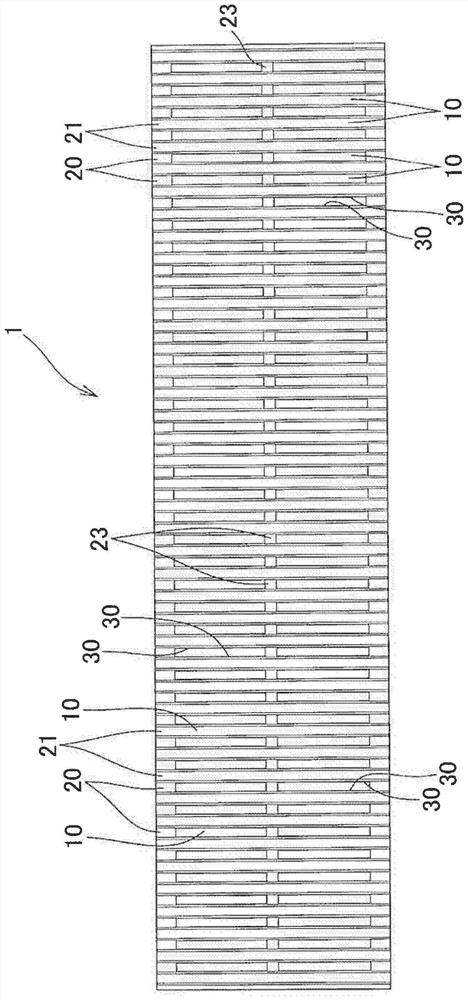
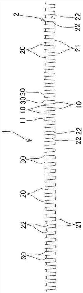
[0049] Such as Figure 1 to Figure 5 As shown, the heat sink 1 of the present invention is provided with through grooves 10 extending in the column direction for passing fluid on the above-mentioned peaks 20 of the metal plate 2 in which a plurality of column-shaped peaks 20 and valleys 21 are alternately formed. , and the opening edge portion 11 of the through groove 10 is provided with a rising piece 30 rising toward the convex side of the peak portion 20, and is installed so that the convex side surface of the valley portion 21 faces the object 4 to be cooled.

[0050] In this embodiment, an example is shown in which the heat sink 1 is attached and used in a state where the convex surface side of the valley portion 21 is directly in contact with the object 4 to be cooled, but it is not limited thereto. For example, although not shown, it may also be configured as A base m...


PUM


Abstract

The invention provides a cooling fin. The heat sink has a through groove (10) extending in the column direction on the peak (20), and has a convex side of the peak (20) on the opening edge (11) of the through groove (10). Stand up sheet (30). Standing pieces (30) are provided on both sides of a pair of opening edge portions (11, 11) facing the through groove (10) and extending in the column direction opposite to each other, and each rising piece (30) is located throughout each opening edge portion ( 11) A long piece that extends substantially over the entire length. Thus, even when the corrugated heat sink is used as a natural convection type, heat stagnation can be prevented and the heat dissipation capability can be maintained, and the interval (pitch) between the intermediate walls can be reduced to achieve The number of peaks and valleys is increased to increase the surface area, and it can be manufactured efficiently and at low cost.

Description

technical field [0001] The present invention relates to a corrugated heat sink that is formed of a metal plate in which a plurality of rows of peaks and valleys are alternately formed, and is attached so that the surface on the convex side of the valleys faces an object to be cooled. Background technique [0002] Currently, such corrugated fins have the problem that the heat fills the inside of the peaks. In a structure in which a fluid is forced to circulate by a fan or the like, such heat stagnation can be prevented, but in a structure using a natural convection type without a fan or the like, damage to the heat dissipation capability cannot be avoided due to the heat stagnation. [0003] Like Patent Document 1, there is proposed a structure in which a louver is formed in an intermediate wall portion between a peak portion and a valley portion by cutting. This causes the fluid to swirl when the fluid is forced to circulate, improving heat dissipation efficiency. However,...

Claims


Application Information

Patent Timeline
Patent Type & Authority Patents(China)
IPC IPC(8): F28F3/02F28F21/08
CPCF28F3/02F28F21/081
Inventor 渡边辉夫渡边秀满渡边泰之渡边刚文
Owner JAPAN
Why Eureka
Try Eureka