Method for realizing naked eye 3D viewing effect by multi-screen splicing special-shaped screen theater

A viewing effect, splicing technology, applied in the installations, optics, instruments and other directions for theaters and circuses, etc., can solve the problems of obvious seams, architectural image deformation, broken lines at the screen splicing, etc., to achieve the perfect unity of perspective relationship, The effect of strong hardware adaptability and perfect mathematical logic

Inactive Publication Date: 2018-08-17
上海溯石数字科技有限公司
View PDF4 Cites 4 Cited by
  • Summary
  • Abstract
  • Description
  • Claims
  • Application Information

AI Technical Summary

Problems solved by technology

In the production of video content in these theaters, the video content is produced in the conventional single-screen mode, and the post-production software is used for splicing. After the implementation, there are the following technical defects: the building image in the film screen is deformed at the junction of the wall and the ground. There are problems with deflection and obvious seams. Each screen cannot map a unified perspective relationship on the set viewing point, and even creases are generated at the splicing of each screen, which makes it impossible to obtain normal viewing effects.

Method used


Image

  • Method for realizing naked eye 3D viewing effect by multi-screen splicing special-shaped screen theater
  • Method for realizing naked eye 3D viewing effect by multi-screen splicing special-shaped screen theater
  • Method for realizing naked eye 3D viewing effect by multi-screen splicing special-shaped screen theater

Examples


Embodiment 2

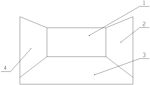
[0058]Embodiment 2. The wall screen B2 and the ground screen 3 constitute an L-shaped screen, including the following steps:

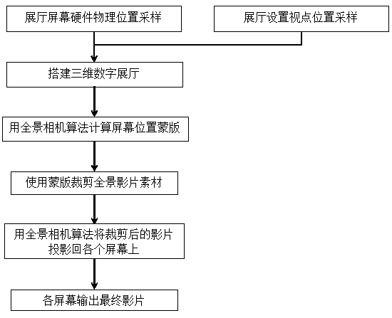
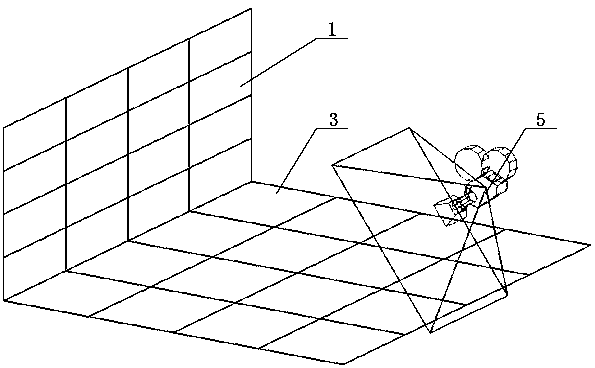
[0059] A. Sampling the physical position of the screen hardware in the exhibition hall, and sampling the position of viewpoint 5 in the exhibition hall at the same time;

[0060] B. Build a three-dimensional digital exhibition hall according to the sampling results;

[0061] C. Based on the viewpoint position of the venue and the screen shapes of the wall screen B2 and the ground screen 3, use the panoramic camera algorithm to calculate the screen position mask;

[0062] D. In the CG software, use the panoramic camera algorithm to make the panoramic expanded video material required for the film, and use the mask to crop the panoramic video material;

[0063] E, use the panoramic camera algorithm to project the cropped film back on the wall screen B2 and the ground screen 3;

[0064] F. The wall screen B2 and the ground screen 3 output the final film;...

Embodiment 3

[0066] Embodiment 3. The wall screen C4 and the ground screen 3 constitute an L-shaped screen, including the following steps:

[0067] A. Sampling the physical position of the screen hardware in the exhibition hall, and sampling the position of viewpoint 5 in the exhibition hall at the same time;

[0068] B. Build a three-dimensional digital exhibition hall according to the sampling results;

[0069] C. Based on the viewpoint position of the venue and the screen shapes of the wall screen C4 and the ground screen 3, use the panoramic camera algorithm to calculate the screen position mask;

[0070] D. In the CG software, use the panoramic camera algorithm to make the panoramic expanded video material required for the film, and use the mask to crop the panoramic video material;

[0071] E, use the panoramic camera algorithm to project the cropped film back on the wall screen C4 and the ground screen 3;

[0072] F. The wall screen C4 and the ground screen 3 output the final film...

Embodiment 4

[0074] Embodiment 4. Any two adjacent wall screens and ground screens 3 form a special-shaped screen, including the following steps:

[0075] A. Sampling the physical position of the screen hardware in the exhibition hall, and sampling the position of viewpoint 5 in the exhibition hall at the same time;

[0076] B. Build a three-dimensional digital exhibition hall according to the sampling results;

[0077] C. Based on the location of the venue's viewpoint and the shape of the special-shaped screen, use the panoramic camera algorithm to calculate the screen position mask;

[0078] D. In the CG software, use the panoramic camera algorithm to make the panoramic expanded video material required for the film, and use the mask to crop the panoramic video material;

[0079] E. Use the panoramic camera algorithm to project the cropped video back to each screen;

[0080] F. Each screen outputs the final movie;

[0081] G. After the movie is projected to the actual screen, when the ...


PUM


Abstract

The invention provides a method for realizing a naked eye 3D viewing effect by a multi-screen splicing special-shaped screen theater. The method is applicable to any wall screen and a ground screen toform an L-shaped screen and is also applicable to the splicing of multiple (2 to 4) wall screens and a ground screen to form a BOX-style full-surrounded theater. With the construction of the L-shapedscreen as an example, the operation steps comprise the steps of (A) sampling the physical position of exhibition hall screen hardware and sampling viewpoint positions for an exhibition hall, (B) building a three-dimensional digital exhibition hall according to a sampling result, (C) calculating a screen position mask by using a panoramic camera algorithm based on a hall viewpoint position and theshape of an L-shaped screen, (D) making a panoramic expanded film material needed by a film with the panoramic camera algorithm in CG software, and cutting the panoramic film material by using a mask, (E) projecting a cut film to each screen by using the panoramic camera algorithm, and (F) allowing each screen to output a final film. According to the method, a multi-screen splicing screen of anyshape has no deformation and no deflection when the screen is viewed on a set viewing point.

Description

technical field [0001] The invention belongs to the technical field of splicing cinemas, and in particular relates to a method for producing multi-screen splicing cinema digital content to obtain a better naked-eye 3D look and feel, which is applicable to CG films produced in full 3D, and is also applicable to the actual shooting of panoramic cameras. Make a video. Background technique [0002] At present, the multi-screen splicing special-shaped screen theater refers to a newly designed wall-ground integrated screen display system through projection or LED display system, which combines the upper and lower images together to form a unified and wide image with a sense of depth. The viewing position has a naked-eye 3D effect. In many planning exhibition halls, cultural and museum exhibition halls, etc., in order to realize arbitrary special-shaped screens (such as double-screen splicing of wall screens and ground screens, pursue a unified composition, and pursue naked-eye 3D...

Claims


Application Information

Patent Timeline
Patent Type & Authority Applications(China)
IPC IPC(8): G02B27/22G09F9/302A63J13/00
CPCA63J13/00G02B30/00G02B30/40G09F9/3026
Inventor 罗星灿安颖
Owner 上海溯石数字科技有限公司
Why Eureka
Try Eureka