Sliding sucking-cup assembly with backpressure sucking cup and curtain wall robot applying same

A sliding disk and suction cup technology, applied in the field of curtain wall robots, can solve the problems of inconvenient production and manufacturing, falling, high processing and installation accuracy, and achieve the effects of convenient manufacturing and application, widening the range of height difference, and improving safety and reliability.

Active Publication Date: 2018-08-21
HUAWAY IOT TECH
View PDF7 Cites 5 Cited by
  • Summary
  • Abstract
  • Description
  • Claims
  • Application Information

AI Technical Summary

Problems solved by technology

The curtain wall robot has the following problems: (1) Due to the limited suction force of the movable suction cup, the height difference between the suction surface of the suction cup and the walking tangential plane of the walking device must be controlled within 2-3mm, otherwise sliding walking cannot be realized, processing and installation High precision, inconvenient to manufacture
Usually, the robot uses multiple movable suction cups to overcome the suction fluctuation caused by the unevenness of the curtain wall. There may be problems with stability, ranging from slowing down of walking speed and pauses to falling

Method used


Image

  • Sliding sucking-cup assembly with backpressure sucking cup and curtain wall robot applying same
  • Sliding sucking-cup assembly with backpressure sucking cup and curtain wall robot applying same
  • Sliding sucking-cup assembly with backpressure sucking cup and curtain wall robot applying same

Examples


Embodiment 1

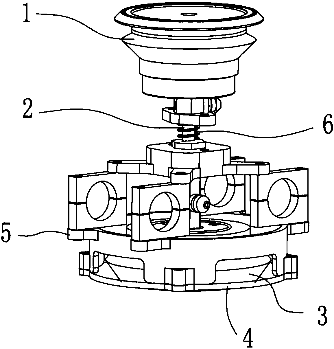
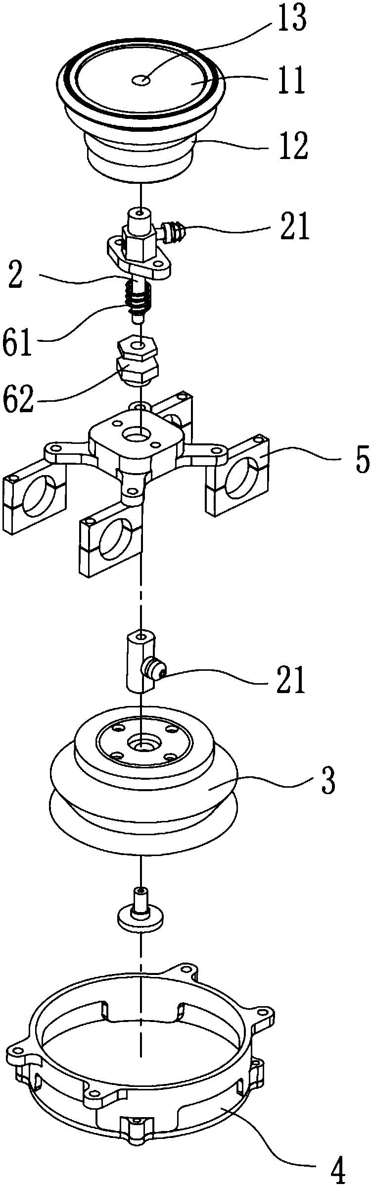
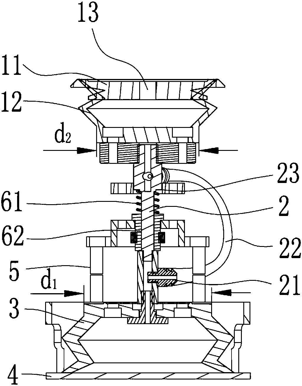
[0032] Such as Figure 1~3 As shown, this embodiment discloses a sliding suction cup assembly with a back pressure suction cup, including a sliding suction cup 1, a connecting rod 2, a back pressure suction cup 3, a vacuum generator (not shown in the figure), a sealing cover 4, and a fixing frame 5. Elastic component6. The elastic component 6 includes a spring 61 and a sleeve 62 . The connecting rod 2 of this embodiment is a split type, the middle part of the connecting rod 2 is a solid structure, and the two ends of the connecting rod 2 are hollow structures, and the hollow structures at both ends of the connecting rod 2 are connected with a joint 21, and the two joints 21 are communicated through a trachea 22.

[0033] The sliding suction cup 1 includes a sealingly fitted sliding disc 11 and an elastic cup 12 , the surface of the sliding disc 11 that fits with the suction plane forms a groove inward, and an air suction hole 13 communicating with the elastic cup 12 is provid...

Embodiment 2

[0037] Such as Figure 4~6 As shown, this embodiment discloses a sliding suction cup assembly with a back pressure suction cup, including a sliding suction cup 1, a connecting rod 2, a back pressure suction cup 3, a vacuum generator (not shown in the figure), a sealing cover 4, and a fixing frame 5. Elastic component6. combine Figure 7 As shown, the elastic component 6 includes a fixed plate 63 , a telescopic slider 64 , four guide rods 65 and four sets of springs 61 . The connecting rod 2 in this embodiment is a hollow structure.

[0038] The sliding suction cup 1 includes a sealingly fitted sliding disc 11 and an elastic cup 12 , the surface of the sliding disc 11 that fits with the suction plane forms a groove inward, and an air suction hole 13 communicating with the elastic cup 12 is provided in the groove.

[0039] The fixing plate 63 is fixedly connected with the fixing frame 5, and the fixing frame 5 is set as a hollow frame body covering the periphery of the back pre...

Embodiment 3

[0042] This embodiment discloses a sliding suction cup assembly with a back pressure suction cup, which is different from the second embodiment in that the structure of the elastic assembly 6 is different. combine Figure 8 As shown, the elastic component 6 includes a fixed plate 63, a telescopic slider 64, four guide rods 65, four groups of springs 61, a sensor 66 and two groups of control push rods 67 connected to the sensor 66 signal, and the sensor 66 is installed on the fixed plate 63 Above, one end of the control push rod 67 is connected with the telescopic slider 64 and the other end is connected with the fixed plate 63 . The control push rod 67 is an electric push rod or a cylinder push rod, and the control push rod 67 is connected with the sensor 66 for signal. Fixed plate 63 is fixedly connected with fixed frame 5, telescopic slider 64 is fixedly connected with connecting rod 2, spring 61 is installed on the guide rod 65, telescopic slider 64 is movably arranged on ...


PUM


Abstract

The invention discloses a sliding sucking-cup assembly with a backpressure sucking cup. The sliding sucking-cup assembly comprises the sliding sucking cup, a connecting rod, the backpressure sucking cup, a vacuum generator, an elastic assembly, a seal cap and a fixing frame. The sliding sucking cup comprises a sliding disc and an elastic leather cup, wherein a groove is inward formed in the surface of the sliding disc, and an air exhausting hole communicated with the elastic leather cup is formed in the groove. One end of the connecting rod is communicated with the elastic leather cup, the other end of the connecting rod is communicated with the backpressure sucking cup, and the portion, communicated with the backpressure sucking cup, of the backpressure sucking cup, of the elastic leathercup is connected with the vacuum generator. The elastic assembly is arranged on the connecting rod, the other end of the backpressure sucking cup is in sealed connection with the seal cap, the area,at the connecting end face of the elastic leather cup and the connecting rod, of the elastic leather cup is S2, and S1 is greater than S2. The invention also discloses a curtain wall robot applying the sliding sucking-cup assembly. The sucking-cup assembly achieves that sucking is prior to pulling and pressing and is good in sucking stability and high in safety reliability when applied to the curtain wall robot.

Description

technical field [0001] The invention relates to curtain wall cleaning equipment, in particular to a sliding suction cup assembly and a curtain wall robot using the same. Background technique [0002] The curtain wall robot is attached to the curtain wall surface with a movable suction cup, and works through the walking device. The movable suction cup structure only includes the suction cup that is in contact with the curtain wall surface. The curtain wall robot has the following problems: (1) Due to the limited suction force of the movable suction cup, the height difference between the suction surface of the suction cup and the walking tangential plane of the walking device must be controlled within 2-3mm, otherwise sliding walking cannot be realized, processing and installation High precision, inconvenient to manufacture. (2) The friction force (F) between the running device and the curtain wall surface is related to the pressure (N) on the running device, the contact surf...

Claims


Application Information

Patent Timeline
Patent Type & Authority Applications(China)
IPC IPC(8): A47L11/38A47L11/40F16B47/00
CPCA47L11/38A47L11/40A47L11/4066F16B47/00E04G23/002
Inventor 刘昌臻陈思鑫
Owner HUAWAY IOT TECH
Why Eureka
Try Eureka