
Laboratory exhaust gas treatment system

A waste gas treatment and laboratory technology, applied in the direction of gas treatment, dispersed particle separation, membrane technology, etc., can solve the problems of energy waste, environmental impact, etc., achieve good purification effect, prevent pollution, and increase the effect of reaction activity

Inactive Publication Date: 2018-08-21
苏州爱源环境科技有限公司
View PDF0 Cites 2 Cited by
  • Summary
  • Abstract
  • Description
  • Claims
  • Application Information

AI Technical Summary

Problems solved by technology

[0002] In the laboratory, chemical experiments will produce harmful exhaust gases such as acid gas and poisonous gas. The pure ventilation equipment can only promote the convection of the environment inside and outside the laboratory, and directly discharge the harmful gas that has not been purified into the atmosphere, causing damage to the environment. negative effect
At present, laboratory waste gas treatment equipment is often not designed according to the characteristics of laboratory waste gas "indeterminate and quantitative", so there is a problem of energy waste, and there is room for improvement in gas purification effect

Method used


Image

  • Laboratory exhaust gas treatment system

Examples


Embodiment Construction

[0032] The present invention will now be further described in detail in conjunction with the accompanying drawings and embodiments. These drawings are all simplified schematic diagrams, only illustrating the basic structure of the present invention in a schematic manner, so it only shows the composition related to the present invention.

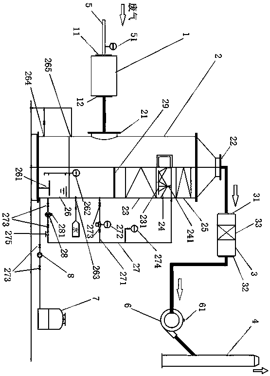
[0033] Such as figure 1 As shown, a laboratory waste gas treatment system is characterized in that it includes a heating device 1 , a waste gas purification tower 2 , a filter device 3 and a gas discharge part 4 . They are connected sequentially by pipes.

[0034] The heating device 1 is provided with a laboratory waste gas inlet 11 and a laboratory waste gas outlet 12 . The laboratory waste gas inlet 11 is connected with the laboratory waste gas collection pipe 5 . The laboratory exhaust gas outlet 12 is connected to the gas inlet 21 arranged on the side wall of the exhaust gas purification tower 2 through a pipeline; the gas outlet 22 of ...


PUM


Abstract

The invention relates to a laboratory exhaust gas treatment system. The laboratory exhaust gas treatment system comprising a heating device, an exhaust gas purification tower, a filter device, an induced draft fan and a gas discharge part is characterized in that the heating device, the exhaust gas purification tower, the filter device, the induced draft fan and the gas discharge part are sequentially connected through a pipeline; from top to bottom, the inner portion of the exhaust gas purification tower is sequentially provided with a liquid storage part, a packing layer, s sprinkler systemand a defogging layer; the liquid storage part is connected with the sprinkler system through a circulating pipe and a circulating pump; the exhaust gas purification tower is connected with a dosing device through the pipeline; frequency conversion devices are respectively arranged on the induced draft fan and the circulating pump; a wind pressure transmitter is disposed on a laboratory exhaust gas collection pipeline connected with the heating device. The laboratory exhaust gas treatment system has the advantages that the arrangement of the heating device facilitates the reaction between exhaust gas and absorption treatment liquid, thus improving purification effect; with the arrangement of the wind pressure transmitter and the frequency conversion devices and with the power supply frequency of the induced draft fan and the circulating pump adjusted according to the wind pressure transmitter, while exhaust gas absorption is ensured to be of good effect, energy savings are maximized, and the effect of energy conservation and emission reduction is achieved.

Description

technical field [0001] The invention relates to the field of waste gas treatment, in particular to a laboratory waste gas treatment system. Background technique [0002] In the laboratory, chemical experiments will produce harmful exhaust gases such as acid gas and poisonous gas. The pure ventilation equipment can only promote the convection of the environment inside and outside the laboratory, and directly discharge the harmful gas that has not been purified into the atmosphere, causing damage to the environment. negative effect. At present, laboratory waste gas treatment equipment is often not designed according to the characteristics of laboratory waste gas "indeterminate and quantitative", so there is a problem of energy waste, and there is room for improvement in gas purification effect. Therefore, it is the problem to be solved by the present invention to provide a laboratory waste gas treatment system with simple structure, energy saving and good purification effect....

Claims


Application Information

Patent Timeline
IPC IPC(8): B01D53/78B01D53/40B01D53/42
CPCB01D53/78B01D53/40B01D53/42B01D2257/93
Inventor 王小莉纪新运朱磊雷
Owner 苏州爱源环境科技有限公司
Learn More