A rectangular supersonic nozzle and its design method

A technology of supersonic nozzle and design method, which is applied in the direction of spraying device, spraying device, heat treatment equipment, etc., and can solve the problems of non-parallel airflow direction at the outlet, limiting the effect of spraying wind, overlapping particles on the surface of workpiece, etc.

Active Publication Date: 2020-11-17
UNIV OF SCI & TECH LIAONING
View PDF6 Cites 0 Cited by
  • Summary
  • Abstract
  • Description
  • Claims
  • Application Information

AI Technical Summary

Problems solved by technology

[0003] However, the circular cross-section supersonic nozzles currently widely used have disadvantages such as little room for adjustment of the outlet radius and difficulty in spraying thinner-diameter rotating workpieces; Inhomogeneous layer, which greatly reduces the quality of cold spray
[0004] The existing three-segment broken-line circular supersonic nozzle has non-parallel airflow direction at the outlet when it is working, the airflow is not easy to concentrate and the wind speed attenuates rapidly, and when using this nozzle to jet quench long-length steel, the diameter of the outlet section is limited. The effect of blowing wind causes the surface temperature and hardness of the section steel to change unevenly
In the spraying process, because the nozzle outlet section is circular, the particles on the surface of the workpiece overlap seriously when spraying the surface of the workpiece, resulting in uneven coating on the surface of the workpiece

Method used


Image

  • A rectangular supersonic nozzle and its design method
  • A rectangular supersonic nozzle and its design method
  • A rectangular supersonic nozzle and its design method

Examples


Embodiment Construction

[0099] In order to make the object, technical solution and advantages of the present invention clearer, the present invention will be further described in detail below in conjunction with the accompanying drawings and embodiments. It should be understood that the specific embodiments described here are only used to explain the present invention, not to limit the present invention.

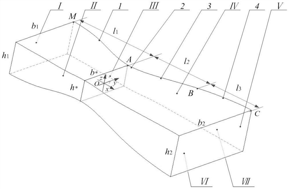
[0100] Such as figure 1 As shown, a rectangular supersonic nozzle is composed of the upper surface IV of the cavity surface, the lower surface VI of the cavity surface, the left surface II of the cavity surface and the right surface VII of the cavity surface. The upper surface of the cavity surface IV and the lower surface of the cavity surface VI are symmetrical about the horizontal plane XOY, the left surface of the cavity surface VI and the right surface of the cavity surface VII are symmetrical about the vertical plane XOZ; the upper surface of the cavity surface IV, the right surface of the ca...


PUM


Abstract

The invention relates to a rectangular supersonic nozzle and a design method thereof. The internal cavity of the nozzle is designed in combination with the movement principle of compressible fluid in a one-dimensional variable-section pipeline and the principle of Mach wave reflection. The upper surface of the cavity and the lower surface of the cavity are about The horizontal plane is symmetrical, and the left surface of the cavity surface and the right surface of the cavity surface are symmetrical about the vertical plane; the upper surface of the cavity surface, the right surface of the cavity surface, the lower surface of the cavity surface and the left surface of the cavity surface are closed to form a cylinder with a rectangular flat slit shape in section. It is composed of a subsonic acceleration zone in the constriction section, a sonic zone in the throat, a supersonic acceleration zone in the front section of the expansion section, and a supersonic parallel zone in the rear section of the expansion section. During the spraying process, the overlapping of sprayed particles can be greatly reduced, the uniformity of the surface coating of the workpiece can be improved, and the quality of cold spraying can be improved; the supersonic jet flow with uniform velocity and temperature distribution can be obtained under the condition of small pressure difference between the inlet and outlet, ensuring There is no shock wave in the flow field inside and outside the nozzle, so as to achieve the ideal spraying or spraying effect.

Description

technical field [0001] The invention relates to a supersonic nozzle, in particular to a rectangular supersonic nozzle and a design method thereof. Background technique [0002] At present, supersonic nozzles are widely used. For example, in supersonic cold spraying technology, supersonic nozzles are used to accelerate spray particles to 300m / s-1200m / s through supersonic carrier gas, and then hit the substrate and deposit on its surface, thus forming A dense coating. [0003] However, the circular cross-section supersonic nozzles currently widely used have disadvantages such as little room for adjustment of the outlet radius and difficulty in spraying thinner-diameter rotating workpieces; The layer is not uniform, so that the quality of cold spraying is greatly reduced. [0004] The existing three-segment broken-line circular supersonic nozzle has non-parallel airflow direction at the outlet when it is working, the airflow is not easy to concentrate and the wind speed atten...

Claims


Application Information

Patent Timeline
Patent Type & Authority Patents(China)
IPC IPC(8): B05B1/02C21D1/62
CPCB05B1/02C21D1/62
Inventor 宋华汪洋付丽华杨建高明昕张影
Owner UNIV OF SCI & TECH LIAONING
Why Eureka
Try Eureka