Warm air blower circuit and cab warm air blower thereof

A heater and circuit technology, which is applied in railway car body parts, railway vehicle heating/cooling, transportation and packaging, etc., can solve the problems of inability to adjust the heating temperature, inability to effectively guarantee the electric heater, etc., and achieves low resistance and electric-heat conversion. High efficiency, no light loss effect

Pending Publication Date: 2018-08-21
ZHUZHOU LINCE GRP +1
View PDF7 Cites 0 Cited by
  • Summary
  • Abstract
  • Description
  • Claims
  • Application Information

AI Technical Summary

Problems solved by technology

However, this setting cannot adjust the heating temperature on the one hand, and on the other hand, when the electric heater and the fan are powered on and off at the same time, it cannot effectively ensure that the waste heat of the electric heater is completely dissipated to the outside of the shell.

Method used


Image

  • Warm air blower circuit and cab warm air blower thereof
  • Warm air blower circuit and cab warm air blower thereof
  • Warm air blower circuit and cab warm air blower thereof

Examples


Embodiment 1

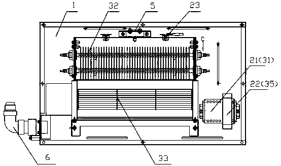
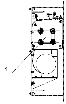
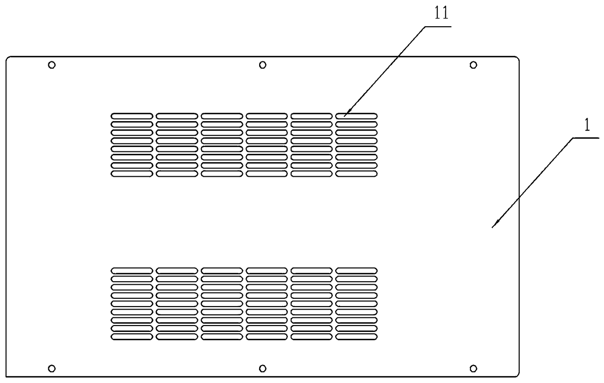
[0031] A cab heater, such as figure 1 As shown, including the chassis 1, the chassis 1 is equipped with such Figure 4 The heater circuit shown includes a control circuit 2 and a heating circuit 3, the control circuit 2 includes a contactor coil 21, the heating circuit 3 includes parallel heating branches and fan branches, and the heating branches include contactor contacts 31 and The heating element 32 is connected in series with the contactor contact 31 , and the fan branch circuit includes a fan 33 for dissipating the heat generated by the heating element 32 to the outside of the chassis 1 .

[0032] The contactor coil 21 and the contactor contacts 31 are an integral contactor. The power supply voltage connected to the control circuit 2 is 110V, and the power supply voltage connected to the heating circuit 3 is 220V. The wires in each circuit are centrally transferred into the chassis 1 through the connector 6. In this embodiment, the contactor is used to control the heati...


PUM


Abstract

The invention belongs to the technical field of locomotive warm air parts, and discloses a warm air blower circuit and a cab warm air blower thereof. The warm air blower circuit comprises a control loop and a heating loop, wherein the control loop comprises a contactor coil, the heating loop comprises a heating branch circuit and a draught fan branch circuit which are connected in parallel, the heating branch circuit comprises a contactor terminal and a heating element connected with the contactor terminal in series, and the draught fan branch circuit comprises a draught fan used for dispersing heat, which is generated by the heating element, to the exterior of a case. A contactor is used for controlling the heating element in the heating loop to heat, low pressure control over high pressure is realized, and the circuit is guaranteed to be stable so as to ensure the heating element to keep working normally; a finned electric heating pipe is adopted, the heating area is large, the heatloss is small, and the warm air blower circuit has the advantages of fast temperature rise, uniform heating, high electricity-heat transformation efficiency and the like.

Description

technical field [0001] The invention relates to the technical field of locomotive heater components, in particular to a heater circuit and a driver's cab heater. Background technique [0002] The cab heating device is an important part of the locomotive cab. It is used to cope with the cold in winter. It can provide a comfortable working environment for the crew and is beneficial to the physical and mental health of the crew. However, due to the small space and complicated layout of the cab, heating The installation of the device has relatively large limitations. Most of the heating equipment used on existing locomotives is installed on the wall, which not only occupies part of the space in the locomotive cab, but also affects the overall aesthetics of the cab, and is not conducive to heating Equipment overhaul and maintenance. [0003] In addition, the current heating equipment (air heater) mainly includes a shell, with a hot air outlet on the side wall of the shell, an el...

Claims


Application Information

Patent Timeline
Patent Type & Authority Applications(China)
IPC IPC(8): B61D27/00
CPCB61D27/0045
Inventor 梁志炜邓姣艳刘荣夫赵日出邹云升吕清帆
Owner ZHUZHOU LINCE GRP
Why Eureka
Try Eureka