Unmanned plane for plant protection

A plant protection drone and machine arm technology, applied in the field of drones, can solve the problems of complex structure of connectors, high manufacturing cost, and low space utilization, and achieve simple locking structure, low manufacturing cost, and simple structure Effect

Active Publication Date: 2018-08-21
重庆零创屹立科技有限公司
View PDF5 Cites 5 Cited by
  • Summary
  • Abstract
  • Description
  • Claims
  • Application Information

AI Technical Summary

Problems solved by technology

[0005] First, the connecting part of the arm and the frame is folded or disassembled horizontally. The horizontal folding is to fold and store the arm and the frame in the horizontal direction. This folding method is more cumbersome to operate and the space utilization rate is low when retracted. ;The disassembly method is to disassemble the whole arm and store it separately. This recycling method is extremely cumbersome and increases the number of contact electrodes and the frequency of use of the contact electrodes, which may easily lead to dangers such as poor contact of the electrodes; Umbrella-shaped folding method, but the structure of the connecting piece used to connect the arm and frame of the UAV in the current umbrella-shaped folding method is relatively complicated, the operation is more cumbersome, and the manufacturing cost is higher;
[0006] Second, the landing gear part is non-retractable. In this way, the working potion can be sprayed on the tripod, and the corrosive potion will shorten the service life of the tripod, and the operation has high requirements for the take-off and landing environment. It needs a relatively flat place to take off and land. At the same time, because it cannot be retracted during operation, it is easy to come into contact with crops, causing safety accidents such as crashes

Method used


Image

  • Unmanned plane for plant protection
  • Unmanned plane for plant protection
  • Unmanned plane for plant protection

Examples


Embodiment Construction

[0045] In order to make the technical means, creative features, goals and effects achieved by the present invention easy to understand, the present invention will be further described below in conjunction with specific illustrations.

[0046] In describing the present invention, it is to be understood that the terms "longitudinal", "radial", "length", "width", "thickness", "upper", "lower", "front", "rear", The orientation or positional relationship indicated by "left", "right", "vertical", "horizontal", "top", "bottom", "inner", "outer", etc. is based on the orientation or positional relationship shown in the drawings , is only for the convenience of describing the present invention and simplifying the description, but does not indicate or imply that the referred device or element must have a specific orientation, be constructed and operated in a specific orientation, and thus should not be construed as limiting the present invention. In the description of the present inventi...


PUM


Abstract

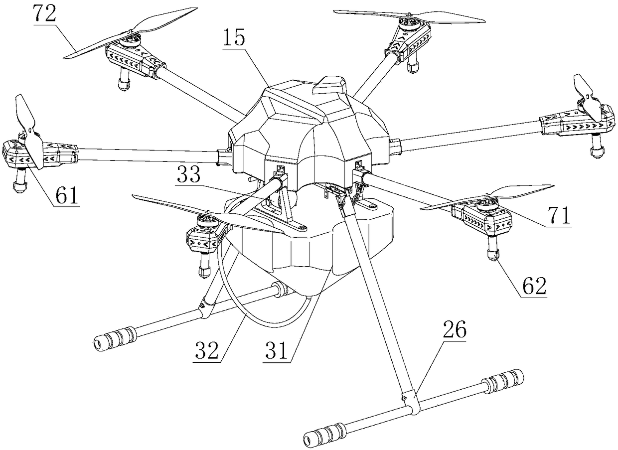
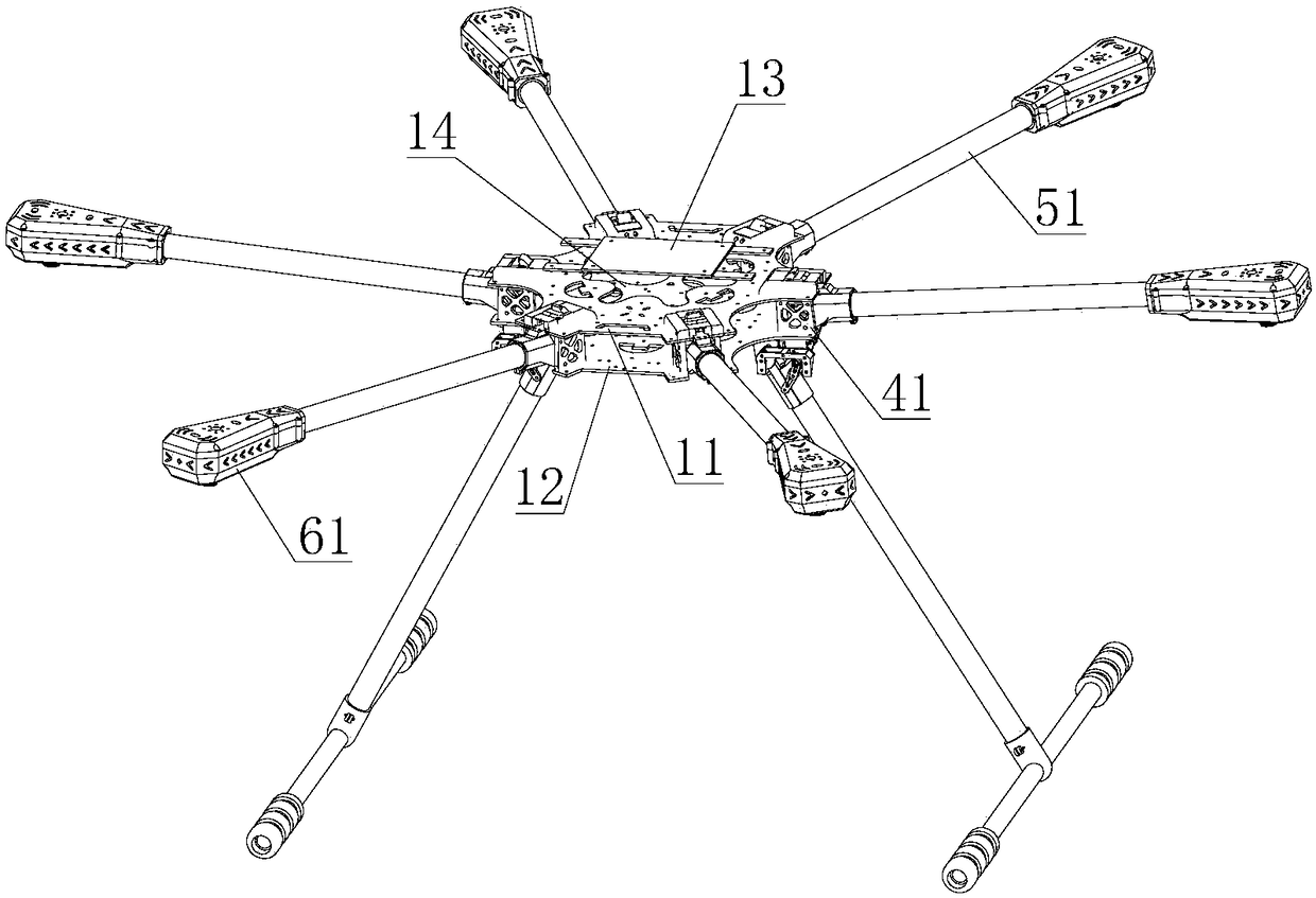
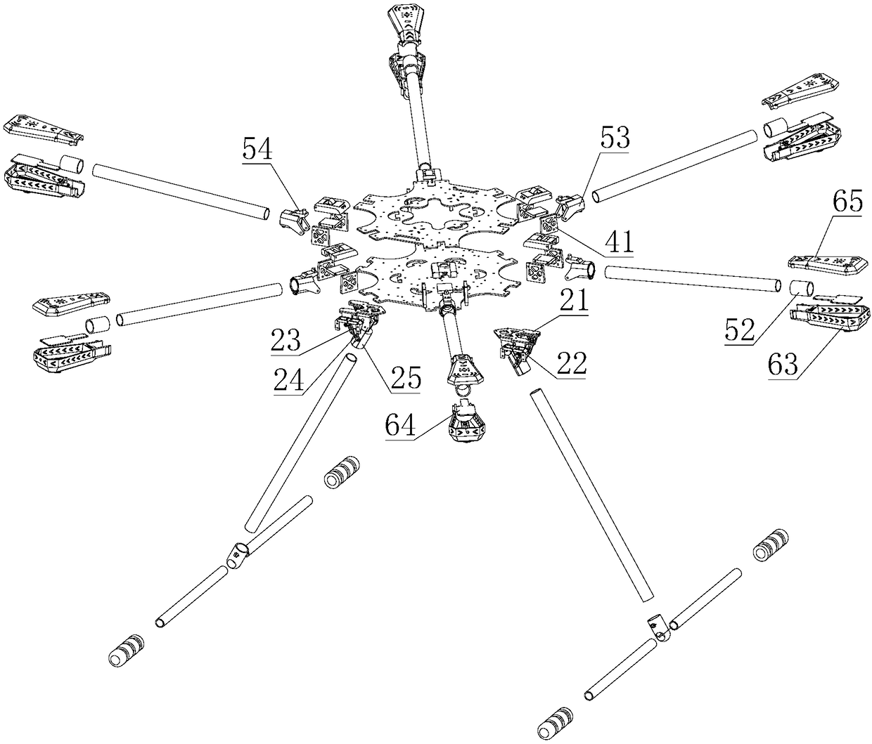
The invention provides an unmanned plane for plant protection. The unmanned plane comprises an installation board mechanism, an undercarriage mechanism, a spraying mechanism, a folding and locking mechanism, a mechanical arm mechanism, a motor base mechanism, and a power mechanism. The installation board mechanism comprises an upper center plate and a lower center plate, which are oppositely arranged. A battery support plate is fixed on the surface of the upper center plate. A flight control plate is fixed on the surface of the lower center plate. The undercarriage mechanism comprises an undercarriage top plate fixedly connected to the bottom surface of the lower center plate. A steering engine base is fixed on the bottom of the undercarriage top plate and is connected to a steering enginerocking bar. The steering engine rocking bar is connected to a rotary sleeve through a rocker arm. The rotary sleeve sleeves a T shape scaffold. The spraying mechanism comprises a medicine barrel, which is fixedly connected to the lower part of the lower center plate, a conduit, which is communicated with the medicine barrel, and an electric water pump, which deliver medicinal liquor in the medicine barrel to the conduit. The folding and locking mechanism comprises a locking mechanism, which is fixed on the surface of the upper center plate and is used to lock the mechanical arm mechanism. The motor base mechanism is fixedly connected to the mechanical arm through an engine base sleeve. The structure is simple, the operation is convenient, and the cost is low.

Description

technical field [0001] The invention relates to the technical field of drones, in particular to a plant protection drone. Background technique [0002] Plant protection UAV, also known as unmanned aerial vehicle, as the name implies, is an unmanned aircraft used for agricultural and forestry plant protection operations. Composed of three parts, the spraying operation can be realized through ground remote control or navigation flight control, which can spray chemicals, seeds, powder, etc. The unmanned small helicopter has low operating height, less drift, can hover in the air, and does not need a special take-off and landing airport. Remote control operation, spraying operators avoid the danger of exposure to pesticides, improve the safety of spraying operations and many other advantages. [0003] At present, plant protection drones are mainly divided into two types: electric plant protection drones and oil-powered plant protection drones. Compared with oil-powered plant pr...

Claims


Application Information

Patent Timeline
Patent Type & Authority Applications(China)
IPC IPC(8): B64C27/08B64D1/18B64C27/14B64C1/06B64C1/30B64D33/08A01M7/00
CPCA01M7/0032A01M7/006A01M7/0082A01M7/0085B64C1/069B64C1/30B64C27/08B64C27/14B64D1/18B64D33/08
Inventor 郑开元
Owner 重庆零创屹立科技有限公司
Why Eureka
Try Eureka