
Double inner cylinder self-sealing rotating compensator

A rotary compensator and self-sealing technology, which is used in expansion compensation devices for pipelines, pipes/pipe joints/fittings, adjustable connections, etc., can solve the problem of large space, reduced sealing performance of rotary compensators, and easy wear of sealing packing. And other issues

Inactive Publication Date: 2018-08-21
贾巧凤
View PDF0 Cites 0 Cited by
  • Summary
  • Abstract
  • Description
  • Claims
  • Application Information

AI Technical Summary

Problems solved by technology

In order to make the rotary compensator have sufficient sealing performance, the pre-tightening force applied to the sealing packing is usually set according to the maximum pressure of the thermal pipeline. The rotating sealing packing of the inner cylinder is easy to wear, which will reduce the sealing performance of the rotary compensator. ; In addition, this type of rotary compensator must be used in pairs, that is, the two outer cylinders are connected through horizontal pipes, and the two inner cylinders are connected to the thermal pipeline through vertical pipes and elbows respectively, forming a gate-shaped structure. When the thermal expansion of the thermal pipeline During cold shrinkage, the inner cylinder rotates in the outer cylinder to compensate the axial expansion and contraction of the heat pipe, eliminate the stress of the heat pipe, and protect the heat pipe; the disadvantage is that when the rotary compensator is used in pairs, it occupies a large space and has Necessary to improve

Method used


Image

  • Double inner cylinder self-sealing rotating compensator
  • Double inner cylinder self-sealing rotating compensator

Examples


Embodiment Construction

[0009] The specific embodiment of the present invention will now be described in conjunction with the accompanying drawings.

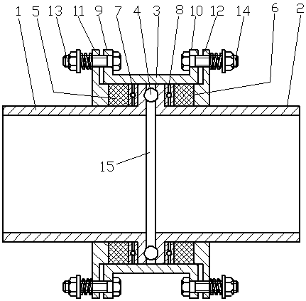
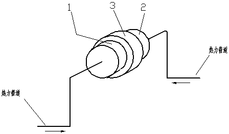
[0010] A double-inner cylinder self-sealing rotary compensator, which includes an outer cylinder 3, characterized in that a first inner cylinder 1 is inserted in the left section of the outer cylinder, a second inner cylinder 2 is inserted in the right section of the outer cylinder, and the first inner cylinder 2 is inserted in the right section of the outer cylinder. The outer diameter of the flange at the right end of the cylinder matches the inner circle of the outer cylinder, the outer diameter of the flange at the left end of the second inner cylinder matches the inner circle of the outer cylinder, and the flange of the first inner cylinder matches the inner circle of the second inner cylinder. Spherical recesses are arranged symmetrically on the end faces facing each other, steel balls 4 are arranged between the spherical recesses, the flange end ...


PUM


Abstract

The invention relates to a double inner cylinder self-sealing rotating compensator which comprises an outer cylinder (3). The compensator is characterized in that a first inner cylinder (1) and a second inner cylinder (2) are inserted into the left section and the right section of the outer cylinder, multiple steel balls (4) are symmetrically arranged between a flange of the first inner cylinder and a flange of the second inner cylinder, first sealing filler (5) is arranged between the first inner cylinder and the outer cylinder and pressed by a first pressing device, and second sealing filler(6) is arranged between the second inner cylinder and the outer cylinder and pressed by a second pressing device. The compensator has the advantages that when the compensator is used, the outer endsof the first inner cylinder and the second inner cylinder are connected with a heating pipeline separately, the compensator does not need to be used in pairs, and the occupied mounting space is small;in addition, a gap exists between the flange of the first inner cylinder and the flange of second inner cylinder, pressure in the heating pipeline is applied to the flange of the first inner cylinderand the flange of the second inner cylinder, the flange of the first inner cylinder and the flange of the second inner cylinder press the sealing filler from inside to outside respectively, and the self-sealing function is achieved.

Description

technical field [0001] The invention relates to a rotary compensator, which is used for thermal expansion and cold contraction of thermal pipelines. Background technique [0002] The structure of the rotary compensator generally includes an outer cylinder and an inner cylinder. One end of the inner cylinder extends into the outer cylinder, and a sealing packing is provided between the outer cylinder and the inner cylinder. The two sides of the sealing packing are clamped to cause radial expansion of the sealing packing to realize There is a seal between the outer cylinder and the inner cylinder. In order to make the rotary compensator have sufficient sealing performance, the pre-tightening force applied to the sealing packing is usually set according to the maximum pressure of the thermal pipeline. The rotating sealing packing of the inner cylinder is easy to wear, which will reduce the sealing performance of the rotary compensator. ; In addition, this type of rotary compen...

Claims


Application Information

Patent Timeline
IPC IPC(8): F16L51/00F16L27/08
CPCF16L51/00F16L27/0832
Inventor 贾巧凤
Owner 贾巧凤
Learn More