A snap-in structure for identification of cables or optical cables

An optical cable and cable technology, which is applied in the field of snap-in structure for cable or optical cable identification, can solve the problems of reduced bonding force between the identification strip and the sheath layer, increased investment in machinery and equipment, trouble for manufacturers, etc. Strong repairability, high manufacturing efficiency, and the effect of reducing investment

Active Publication Date: 2019-11-05
TIANJIN JINHANG COMP TECH RES INST
View PDF5 Cites 0 Cited by
  • Summary
  • Abstract
  • Description
  • Claims
  • Application Information

AI Technical Summary

Problems solved by technology

[0007] In short, the above solution is to extrude a marking strip on the sheath of the optical cable. Of course, the marking strip may have the function of luminous and bright light recognition. However, this method has the following main defects: (1) Multi-color heads are required, Or a variety of molds, extrusion or injection molding at the same time, this method not only increases the investment in machinery and equipment, but also uses more space, the bonding force between the marking strip and the sheath layer will also become smaller over time, and the resistance The torsion ability is relatively poor; (2) The management of various color bars and molds is troublesome, and different outer diameters require different color separation molds or sheath extrusion molds, resulting in increased costs
[0009] The cable or optical cable identification structure in the prior art is on the sheath formed by extrusion, which cannot be replaced, let alone the color. When the color fades or is damaged, only the entire cable can be replaced, or the entire cable can only be replaced Re-extrusion can only be achieved by stripping the relevant parts. This method affects the construction speed, and at the same time causes an increase in cost, waste of materials, etc.
[0010] The above methods have brought great trouble to the manufacturer.

Method used


Image

  • A snap-in structure for identification of cables or optical cables
  • A snap-in structure for identification of cables or optical cables
  • A snap-in structure for identification of cables or optical cables

Examples


Embodiment 1

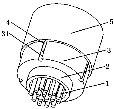
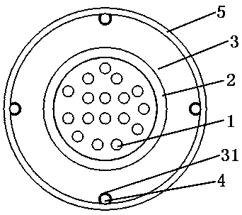
[0045] please see figure 1 with figure 2 , a cable or optical cable that is easily identifiable under bright light and dark light conditions, including a cable or optical cable core 1, a protective layer covering the cable or optical cable core 2, and an extrusion coating outside the protective layer The sheath layer 3 has at least one sheath groove 31 on the outer edge of the sheath layer, and is characterized in that there is a night vision unit 4 in the sheath groove, and the sheath layer and the night vision unit are covered with a The transparent light-transmitting strip 5; the night vision unit is a linear or rope-like structure that absorbs visible light and emits visible light.

[0046] The above-mentioned cable or optical cable that is easy to identify under bright light and dark light conditions, wherein the sheath grooves are one or two or three or four or other multiple, and can be symmetrical or non-symmetrical when there are multiple grooves. Symmetrically dis...

Embodiment 2

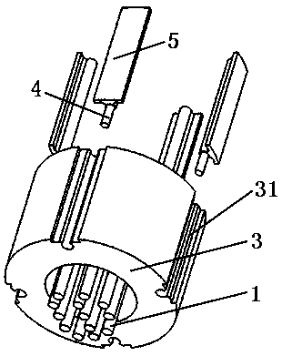
[0052] please see Figure 3 to Figure 5 , a cable or optical cable that is easily identifiable under bright light and dark light conditions, comprising a cable or optical cable core 1, a sheath layer 3 covering the cable or optical cable core, and the outer edge of the sheath layer has at least one The sheath groove 31 is characterized in that: the light-transmitting strip 5 is embedded in the sheath groove; the sheath groove is composed of the first part 311 of the sheath groove, the second part 312 of the sheath groove, the The third part 313 and the fourth part 314 of the sheath groove are formed, one end of the third part of the sheath groove is connected with the first part of the sheath groove and the second part of the sheath groove, and the third part of the sheath groove The other end is connected to the fourth part of the sheath groove, the first part of the sheath groove is connected to the second part of the sheath groove, and the outer edges of the first part of t...

Embodiment 3

[0064] please see Image 6 with Figure 7 , and refer to Figure 3 to Figure 5 , a kind of cable or optical cable that is easy to identify under bright light and dark light conditions, basically the same as the implementation example 2, the difference is that: the fourth part 54 of the light-transmitting strip has an open groove 56 communicating with the night vision hole 55, this In this way, the night vision unit can be inserted into the night vision hole 55 through the opening groove 56, which not only saves the material of the fourth part 54 of the light-transmitting strip, but also makes it more convenient to manufacture.

[0065] In the present invention, the night vision unit is very easy to replace, but in the prior art, the extruded one cannot be replaced, and the related materials can only be re-extruded after being stripped off. Therefore, the present invention is more convenient and flexible to replace.

[0066] In Embodiments 2 and 3 of the present invention, th...


PUM

PropertyMeasurementUnit
angleaaaaaaaaaa
elongation at breakaaaaaaaaaa

Abstract

The invention belongs to the technical field of cables, and relates to a snap-in structure for identification of cables or optical cables, which is composed of a light-transmitting strip and a night vision unit. The first / second part is connected and the outer edge of the first / second part is on the surface of the same cylinder, the upper end of the third part of the light-transmitting strip is connected with the first and second parts of the light-transmitting strip, and the third part of the light-transmitting strip The lower end of the part is connected with the fourth part of the light-transmitting strip, and there is a night vision hole inside the fourth part of the light-transmitting strip, and the size gradually increases from the lower end to the upper end of the third part of the light-transmitting strip; the first to third parts of the light-transmitting strip It is transparent; the night vision unit is located in the night vision hole, and the night vision unit can emit light at night or under dark light conditions. The invention can be conveniently used in various optical cables, electric cables, photoelectric composite cables or photoelectric composite cables, and has multiple beneficial technical effects such as simple structure, luminous and bright light identification, easy replacement, and strong versatility.

Description

[0001] This application claims the priority of a utility model patent application titled: A snap-in structure for identification of cables or optical cables, with an application date of April 4, 2017, and application number: 201720343968.3. technical field [0002] The invention belongs to the technical fields of light, cable, electric power and communication construction, and in particular relates to a snap-in structure for identification of cables or optical cables. Background technique [0003] With the rapid development of the communication industry, the application of optical fiber cables, wires and cables is becoming more and more extensive. In the prior art, the outdoor applications of cables mainly include: pipelines, buried, and overhead. Since the cables belong to different owners, However, they may be laid on the same pipe and pole. In this case, it brings great inconvenience to the maintenance and repair personnel. Since the printing on the surface of the cable wi...

Claims


Application Information

Patent Timeline
Patent Type & Authority Patents(China)
IPC IPC(8): H01B7/36
CPCH01B7/368
Inventor 袁红
Owner TIANJIN JINHANG COMP TECH RES INST
Why Eureka
Try Eureka