
A method of cleaning a charge air cooler and an internal combustion engine

一种增压空气冷却、内燃发动机的技术,应用在内燃活塞发动机、燃烧发动机、机器/发动机等方向,能够解决热交换能力降低、难以控制增压空气温度等问题

Active Publication Date: 2018-08-21
WARTSILA FINLAND OY
View PDF5 Cites 1 Cited by
  • Summary
  • Abstract
  • Description
  • Claims
  • Application Information

AI Technical Summary

Problems solved by technology

[0010] Reduced heat exchange capacity actually means increased circulation of cooling fluid and somewhat more difficult control of charge air temperature

Method used


Image

  • A method of cleaning a charge air cooler and an internal combustion engine
  • A method of cleaning a charge air cooler and an internal combustion engine
  • A method of cleaning a charge air cooler and an internal combustion engine

Examples


Embodiment Construction

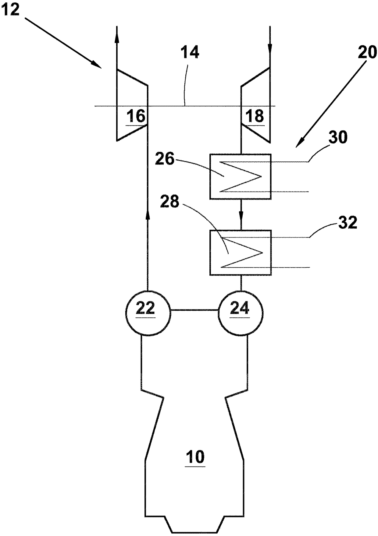
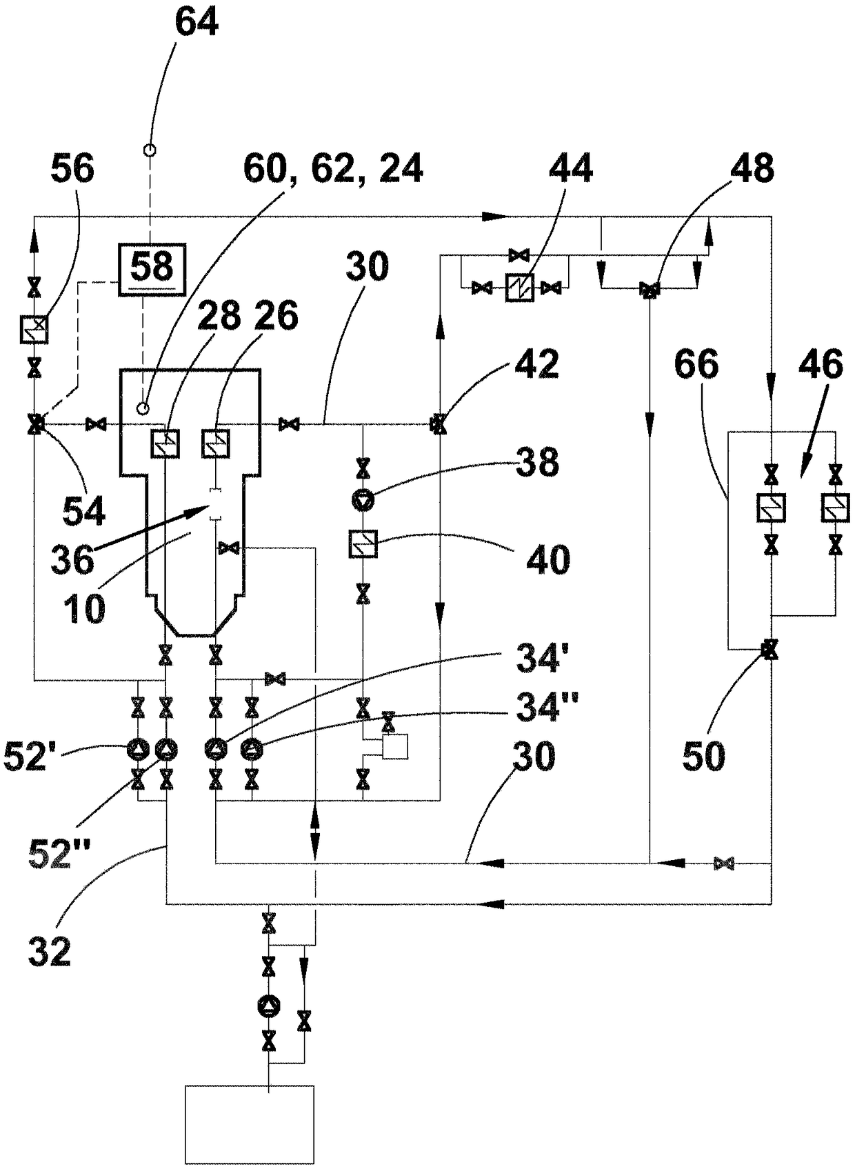
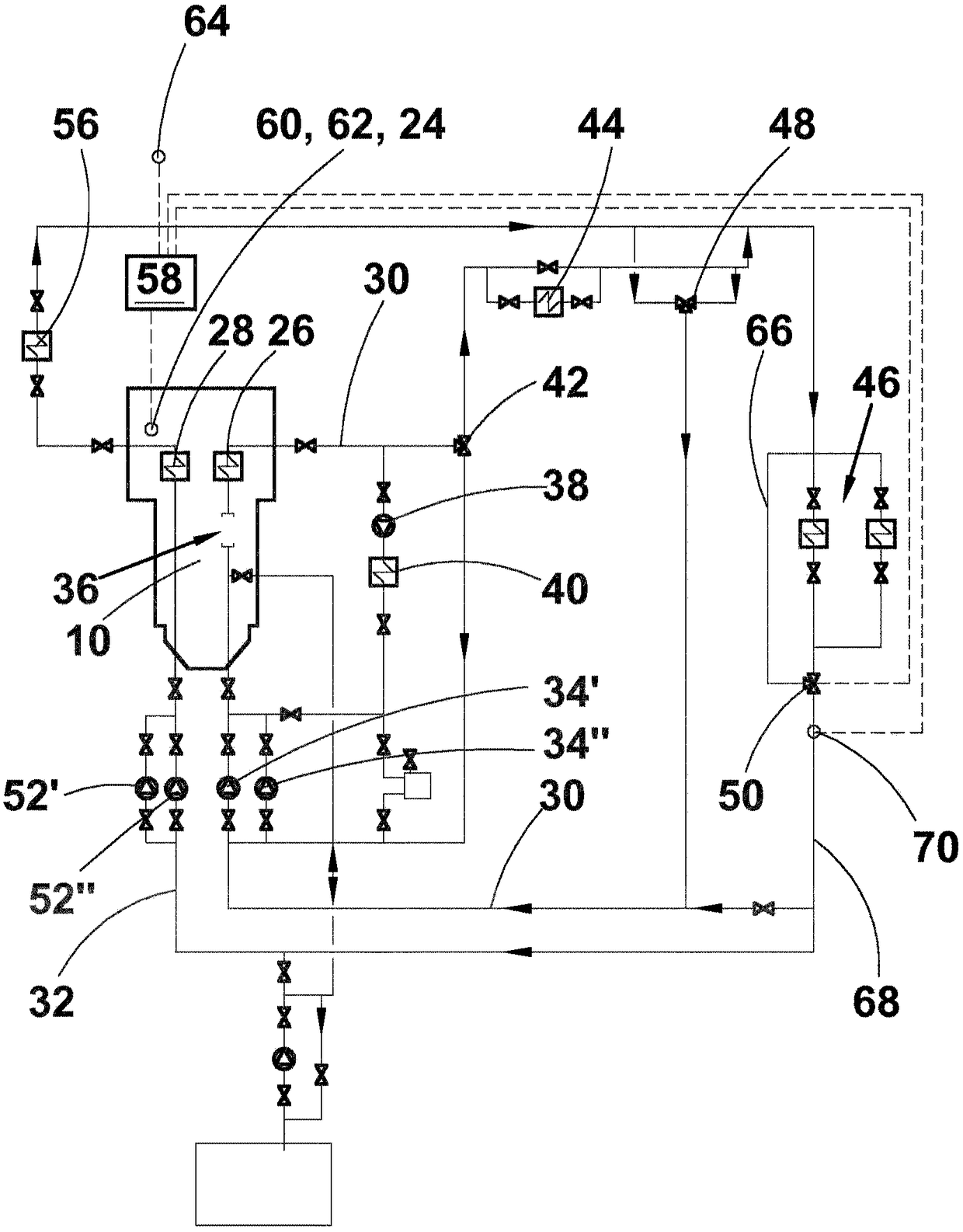
[0033] figure 1A prior art internal combustion engine 10 is discussed comprising: a cylinder block having at least one cylinder and at least one cylinder head, and having at least one turbocharger 12 having a shaft 14, a turbine 16 and compressor 18 ; and an intercooler arrangement 20 between compressor 18 and engine 10 . Turbine 16 of turbocharger 12 communicates with an exhaust manifold 22 at a cylinder head of engine 10 , and compressor 18 communicates with a charge air receiver 24 at a cylinder head of engine 10 . The intercooler structure 20 includes two charge air coolers provided with heat exchange surfaces, namely a high temperature (HT) charge air cooler 26 with HT heat exchange surfaces and a low temperature (LT) intercooler with LT heat exchange surfaces. Compressed air cooler 28 , the charge air cooler is arranged such that charge air leaving compressor 18 is directed first into HT charge air cooler 26 and subsequently into LT charge air cooler 28 . The HT charge...


PUM


Abstract

The present invention relates to a turbocharged internal combustion engine provided with means for flushing dirt periodically from the heat exchange surfaces of the LT- charge air cooler by using water condensed on the heat exchange surfaces for the flushing.

Description

technical field [0001] The invention relates to a cleaning method of a charge air cooler of an internal combustion engine as discussed in the preamble of claim 1 and to an internal combustion engine as discussed in the preamble of claim 10 . Background technique [0002] Both economical and environmental aspects now lead users of internal combustion engines to require engines with the lowest possible specific fuel consumption. This need has led to the use of devices that increase the charge of air in the cylinders of the engine compared to normally aspirated engines. The first such device is usually called a supercharger and its main task is to increase the pressure or density of the air, that is, to compress the air entering the cylinders of the engine. There are two main types of superchargers. The first is a turbocharger, commonly called a turbine, which is a unit that has a turbine wheel and a compressor wheel on the same shaft so that the engine's exhaust gas drives t...

Claims


Application Information

Patent Timeline
Patent Type & Authority Applications(China)
IPC IPC(8): F02B29/04F01P7/16F01P3/18F01P7/14F01P11/06F28D21/00
CPCF02B29/0412F02B29/0443F02B29/0493F01P2011/065F01P2060/02F02D2200/0406F02D2200/0414F02D2200/0418F28D2021/0082F28G9/00Y02T10/40F02D41/22F02D41/0007F01P11/06F02B29/0468F02B29/0462Y02T10/12F01P3/20
Inventor V·海拉卡里J·库亚拉V-V·马基嫩K·涅米宁
Owner WARTSILA FINLAND OY
Learn More