
Electrically-controlled tail-end-steerable mechanical arm

A steering machine, electronic control technology, applied in the field of robots, can solve the problems of uneven transition marks, increase in volume, slow down movement speed, etc., to achieve the effect of fast movement of the end, increase the atomization effect, and speed up the drying speed.

Active Publication Date: 2018-08-24
华南智能机器人创新研究院 +1
View PDF5 Cites 1 Cited by
  • Summary
  • Abstract
  • Description
  • Claims
  • Application Information

AI Technical Summary

Problems solved by technology

In common articulated robots, the driving components of each arm are installed on the joints connected to the forearm. As the number of arms increases, the load on each arm will increase accordingly, resulting in an increase in the volume of the driving power components of the arm and an increase in the movement speed of the arm. Problems such as slowing down and reducing the accuracy of the arm are not conducive to the high-speed and miniaturization of joint robots
[0003] The use of robots for painting operations is more common in robot applications. During the painting process, if an accident such as a material outage occurs and the paint supply is cut off, even if the parts in the job are repainted, due to the different drying time of the paint, the new paint There will be uneven transition marks at the junction with the old paint, and the parts can only be scrapped or reprocessed, which is a waste of cost

Method used


Image

  • Electrically-controlled tail-end-steerable mechanical arm
  • Electrically-controlled tail-end-steerable mechanical arm
  • Electrically-controlled tail-end-steerable mechanical arm

Examples


Embodiment Construction

[0058] The following will clearly and completely describe the technical solutions in the embodiments of the present invention with reference to the accompanying drawings in the embodiments of the present invention. Obviously, the described embodiments are only some, not all, embodiments of the present invention. Based on the embodiments of the present invention, all other embodiments obtained by persons of ordinary skill in the art without creative efforts fall within the protection scope of the present invention.

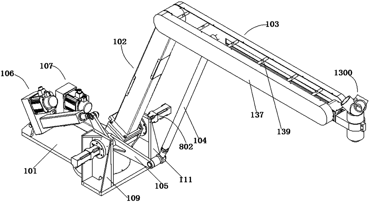
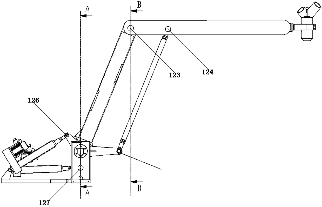
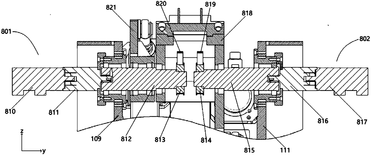
[0059] figure 1 It shows a schematic diagram of the three-dimensional structure of the electronically controlled terminal steerable arm of the embodiment of the present invention, figure 2 Shows the front view of the electronically controlled terminal steerable arm of the embodiment of the present invention, Figure 5 It shows the top view of the multi-axis manipulator module of the embodiment of the present invention. In order to clearly show the transmission st...


PUM


Abstract

The invention provides an electrically-controlled tail-end-steerable mechanical arm. The electrically-controlled tail-end-steerable mechanical arm comprises a mechanical arm module and a painting module, wherein a driving element of the mechanical arm module is arranged on a platform at the bottom part; a first arm and a second arm do not have additional weight, excepting dead weight and the weight of supporting connecting rods, so that the characteristics such as quick moving of a tail end are realized; a working tail end which can be gyrated and rotated on own axis is mounted on the tail endof the second arm, thus the freedom of motion is increased, and various working demands are met; a gyrating driving assembly and a rotating driving assembly at the working tail end are mounted on theplatform, and moving parts of the driving assemblies are lighter than an existing mechanical arm; a painting head of the painting module is provided with pressure maintaining measures, the painting can be continuously performed for a while in case of material cutting off by accident, and thus unqualified products caused by material cutting off can be avoided; the painting head has the heating function and is capable of heating paint, so that the air temperature is increased while the atomizing effect of the paint is increased, and the paint can be quickly dried by air.

Description

technical field [0001] The invention relates to the field of robots, in particular to an electronically controlled terminal steerable machine arm. Background technique [0002] Robots can be divided into parallel robots and serial robots. Among them, the common type of serial robots is articulated robots. In common articulated robots, the driving components of each arm are installed on the joints connected to the forearm. As the number of arms increases, the load on each arm will increase accordingly, resulting in an increase in the volume of the driving power components of the arm and an increase in the movement speed of the arm. Problems such as slowing down and reducing the accuracy of the arm are not conducive to the high-speed and miniaturization of joint robots. [0003] The use of robots for painting operations is more common in robot applications. During the painting process, if an accident such as a material outage occurs and the paint supply is cut off, even if th...

Claims


Application Information

Patent Timeline
Patent Type & Authority Applications(China)
IPC IPC(8): B05B1/24B05B12/08B05B13/04B05B15/625B05B15/68B25J11/00B25J18/00
CPCB05B1/24B05B12/087B05B13/0431B25J11/0075B25J18/00B05B15/625B05B15/68
Inventor 谭军民罗少锋赵中兴胡寒
Owner 华南智能机器人创新研究院
Learn More