
Spring machine cutter device

A technology of spring machine and cutter, which is applied in the field of spring machine, can solve the problem of inconvenient replacement of cutter, achieve the effect of reducing labor intensity and avoiding rotation

Active Publication Date: 2018-08-24
东莞市鑫鼎机械设备有限公司
View PDF5 Cites 1 Cited by
  • Summary
  • Abstract
  • Description
  • Claims
  • Application Information

AI Technical Summary

Problems solved by technology

[0004] The purpose of the present invention is to solve the problem of inconvenient replacement of the cutter in the spring machine in the prior art, and propose a spring machine cutter device

Method used

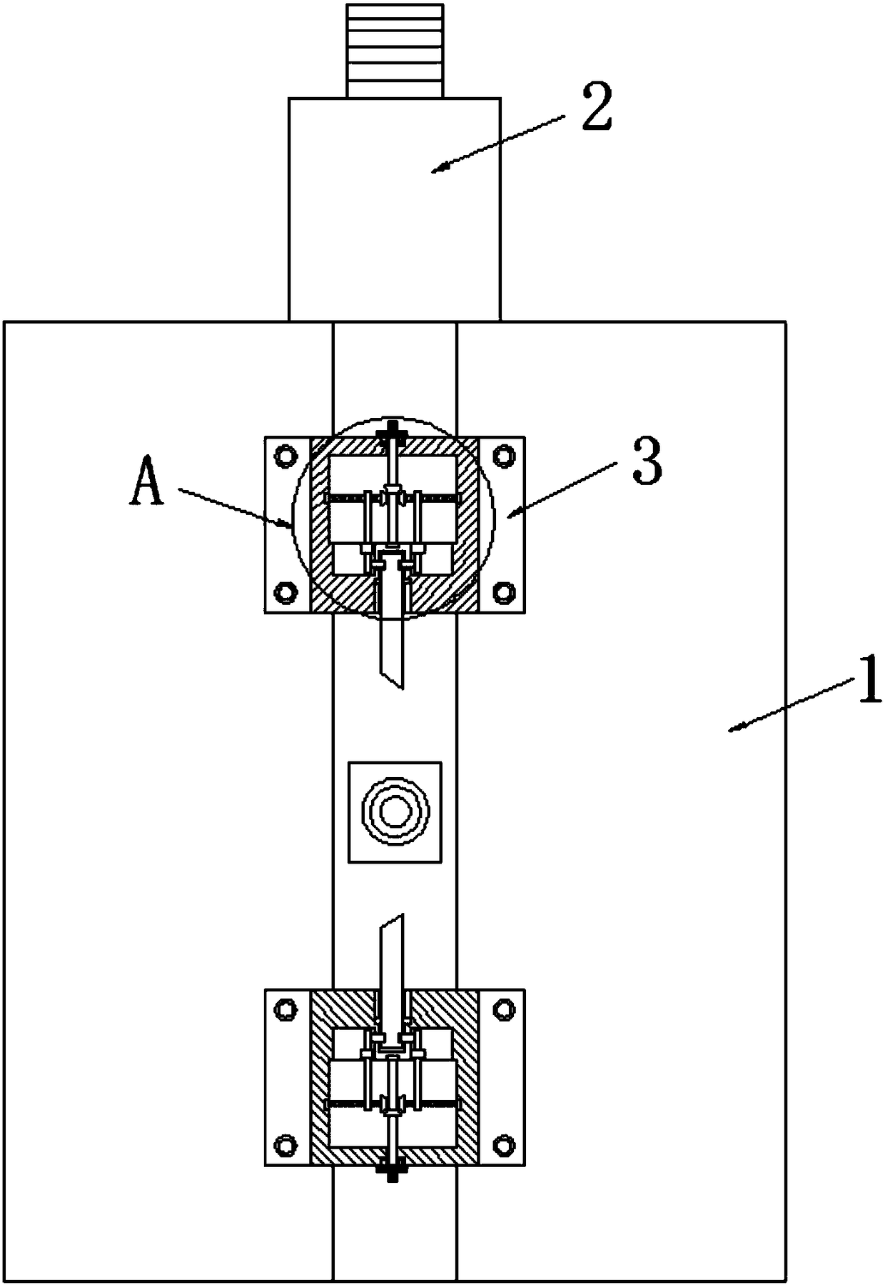
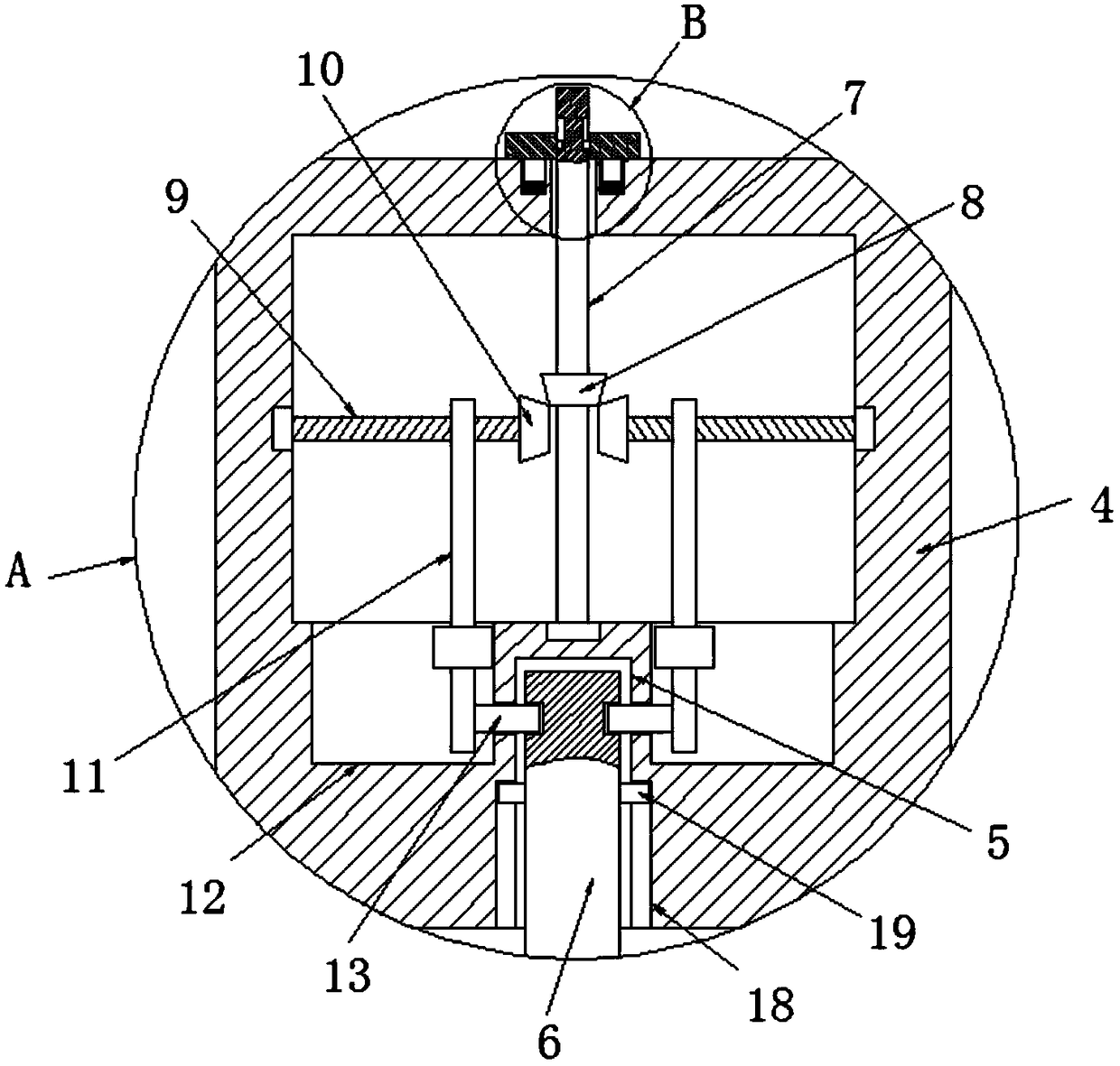
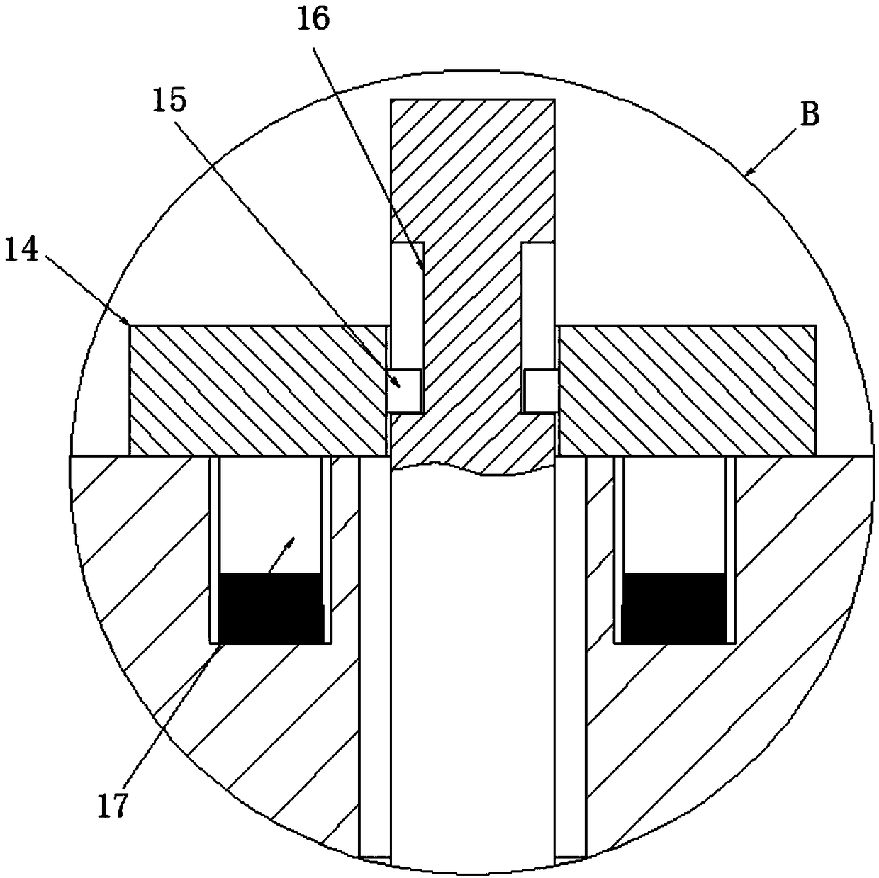

Image

  • Spring machine cutter device
  • Spring machine cutter device
  • Spring machine cutter device

Examples


Embodiment Construction

[0021] The following will clearly and completely describe the technical solutions in the embodiments of the present invention with reference to the accompanying drawings in the embodiments of the present invention. Obviously, the described embodiments are only some, not all, embodiments of the present invention.

[0022] In describing the present invention, it should be understood that the terms "upper", "lower", "front", "rear", "left", "right", "top", "bottom", "inner", " The orientation or positional relationship indicated by "outside", etc. is based on the orientation or positional relationship shown in the drawings, and is only for the convenience of describing the present invention and simplifying the description, rather than indicating or implying that the referred device or element must have a specific orientation, so as to Specific orientation configurations and operations, therefore, are not to be construed as limitations on the invention.

[0023] refer to Figure ...


PUM


Abstract

The invention discloses a spring machine cutter device which comprises a device body, a bidirectional cutter mechanism and a transmission mechanism. The bidirectional cutter mechanism comprises two cutter bases and two cutters. Cutter storing grooves are formed in the opposite side walls of the two cutter bases correspondingly. Cutters are movably arranged in the cutter storing grooves. Cavities are formed in the portion, located above the cutter storing grooves, in the cutter bases. Clamping mechanisms are arranged in the cavities. The spring machine cutter device is convenient to operate, staff can disassemble and replace the cutters and the cutter bases conveniently, and pulling intensity of the staff is reduced.

Description

technical field [0001] The invention relates to the technical field of spring machines, in particular to a spring machine cutter device. Background technique [0002] The traditional spring cutter device is a motor controlled by a numerical control system. The motor drives a three-stage deceleration gearbox to rotate the crankshaft at a low speed, and then the slider installed in the cutter seat moves through the crank guide mechanism, and the slider pushes the cutter. Realize the purpose of cutting steel wire. [0003] After searching, the Chinese patent authorization number is CN102836934B, which discloses a spring machine cutter device, including a two-way cutter mechanism and a transmission mechanism. The two-way cutter mechanism includes a slider, an upper cutter seat and a lower cutter seat. , the upper cutter seat and the lower cutter seat are both arranged on the slider; the transmission mechanism is fixedly connected with the slider. The upper cutter and the lower...

Claims


Application Information

Patent Timeline
IPC IPC(8): B21F11/00
Inventor 钟伟艺
Owner 东莞市鑫鼎机械设备有限公司
Learn More